User Manual For - CONTROLLER/DATA RECORDER MultiCon CMC-99/141
7.10.5. Examples of build-in output configuration s
7.10.5.1.
Application of the output for R45 modules
See also: Appendices 8.13. R45, R81, R65, R121 - RELAY MODULES and Appendices
8.7. RT4 , RT6 – RTD MEASUREMENT MODULES.
Task:
Let's say that we would like to control temperature (around 30°C) in some room by
switching ON and OFF an electric heater. The hysteresis should be 5°C. The temperature is
measured using a PT100 sensor and
RT4
input module, and let the heater is controlled using
an internal 5A relay (
R45
module).
Solution:
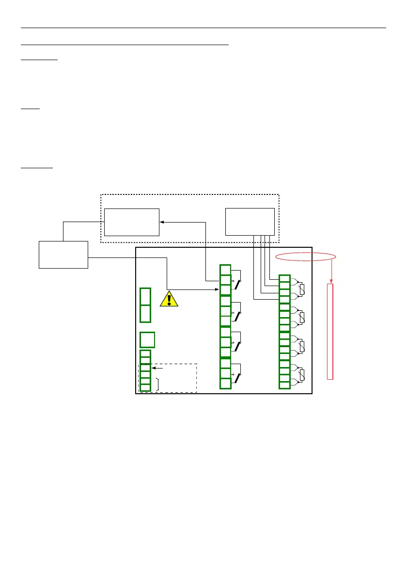
First configure the device as described below, then connect the object and power supply
as shown on
Fig. 7.92
.
Fig. 7.92.Schematic diagram for the RTD input and Relay output modules
To control temperature in object shown on
Fig. 7.92
, it is necessary to configure one
Logical channel
and
Relay output
.
For reading PT100 sensor temperature:
– touch screen and press the
Menu
button,
– press the
Device configuration
button,
– enter the
Logical channels
menu,
– using the arrows in the top navigation bar, select any
Logical channel
such as
1
,
– in
Name
parameter write
Feedback
,
–
Mode
parameter set as
Hardware input
,
–
Source
parameter set as
Inp.A1 : RTD
(see
Fig. 7.92
),
162
R45
4 relay outputs 5A/250V
n01
n02
n03
n04
n05
n06
n07
n08
n09
n10
n11
n12
OUT 1
OUT 2
OUT 3
OUT 4
PT100
sensor
Slot A
Inp.A1 : RTD
Inp.A2 : RTD
Inp.A3 : RTD
Inp.A4 : RTD
RT4
4 RTD inputs
IN1 IN2 IN3 IN4
n01
n02
n03
n04
n05
n06
n07
n08
n09
n10
n12
n13
n14
n15
n16
n11
Heater
Power supply
L
N
Slot C
Out.C1 : Relay
Controlled object
Power supply
(depending on version)
1
2
8
5
6
7
3
4
+24V DC ±5%
(
Imax. = 200mA)
digital input
0/15..24V DC
RS-485
GND
GND
A+
B-
isolated
SERVICE