User Manual For - CONTROLLER/DATA RECORDER MultiCon CMC-99/141
7.9.2. Built-in inputs - Input modules
Short description of configuration of the physical input is shown in
Fig.
4.9
÷
Fig. 4.21
and is
dependent on specific measurement modules. In the
Built-in inputs
menu for the module the
user can:
– change the ranges covered (depending on module), see
8. APPENDICES
,
– change the connection method - it depends on the module (see
8. APPENDICES
),
e.g. in the RTD module the user can select 2, 3 and 4-wire connections,
– change the type of reading of the input signal - depending on the module, e.g.
a thermocouple module can read the temperature and voltage,
– change operation of the module - e.g. in counter module user can select function
mode: add mode ("Function mode"="A+B"), subtract mode ("Function mode"="A-B"),
quadrature mode 1 ("Function mode"="quad 1"), quadrature mode with increased
resolution ("Function mode"="quad 4"),
Parameters common for built-in inputs modules:
–
Name
- each built-in input already has a name given by the device and user cannot
change it, description of the
Name
parameter see
Fig.
7.75
,
–
Unit
– it is related to channel source data, for built-in modules default unit appears
automatically,
–
Mode
– sets type of measurement; depending on module it sets measurement range
or way of measurement,
–
Low Limit
– above this value in logical channel, low alarm state appears, displayed
as
Lo
,
–
High Limit
– above this value in logical channel, high alarm state appears, displayed
as
Hi
,
Other parameters of
Built-in inputs
menu depend on the modules installed in the device.
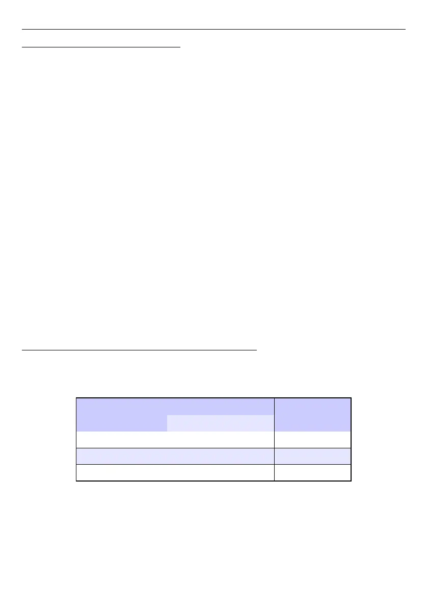
7.9.3. Built-in inputs - Binary input Inp.X2 : Digital 24V
The device has a built-in digital input, which can be used, for example as a switch for
a process. Specifications of digital input are included in
Chapter 3. TECHNICAL DATA
. This
digital input has levels:
input voltage [V]
digital input
min max
low level 0 1 0
prohibited level >1 <8 x
high level 8 24 1
Tab. 7.5 Voltage levels for Binary input Inp.X2 : Digital 24V
The
Binary input
has 2 parameters:
–
Name
– each built-in input already has a name given by the device and user cannot
change it, for description of
Name
parameter see
Fig.
7.75
,
139