User Manual For - CONTROLLER/DATA RECORDER MultiCon CMC-99/141
– for
Controller output
parameter block:
•
in
Offset
parameter write
0
,
•
in
Low output limit
write
0 mA
,
•
in
High output limit
write
20 mA
,
After leaving the configuration save settings. In next steps we should set Logical channels
(examples of logical channel configuration are in
Chapter 7.8.11. Examples of Logical
Channels configuration
, especially
7.8.11.8. Application of Logical channel in the
Controller mode
), set Modbus for Slave device (examples for Modbus configuration are in
Chapter 7.15.4. Modbus - Example of Modbus protocol configuration in the device
,
examples of external outputs configuration which will communicate with Slave device via RS-
485 are in
Chapter 7.11.4. Examples of external output configurations
).
7.13.2.2.
Application of the Controllers in cooperation with heater which is controlled
by SSR output.
See also:
Chapter 7.13. CONTROLLERS
and
Chapter 7.10.3. Build-in output - PWM
(Pulse-width modulation) mode for SSR relay output
.
Task:
The task is to configure the controller which will control the heater using SSR output in
order to obtain a constant object temperature. A logical channels with set point value and
temperature from thermocouple type K sensor are connected to the controller. Due to fact that
choosing of PID controller is not matter of the task, we can use following demonstration
values: P=5, I=10, D=1. We do not want that the controller respond for deviation lower than
2ºC. On controller's output set 4-20mA range, because that is the range of the converter we
use to control the heater in this task.
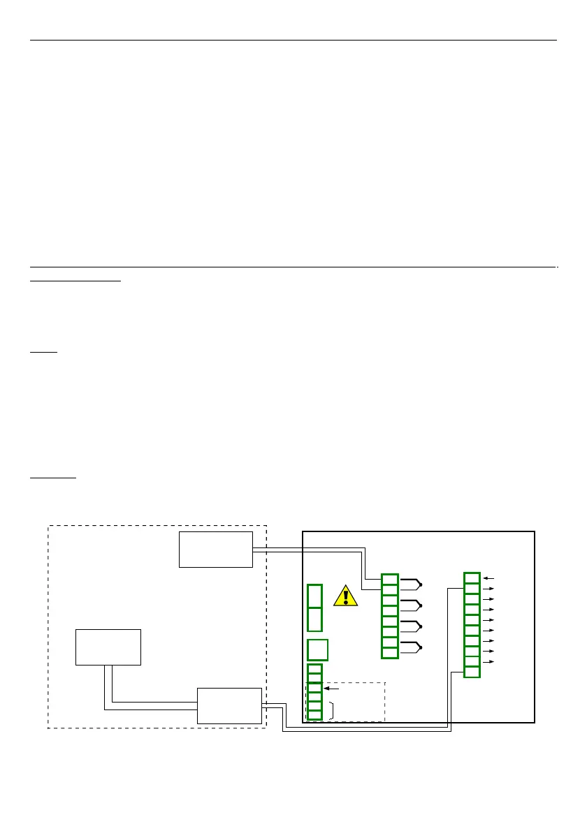
Solution:
First configure the controller, then connect the type K thermocouple and Current
converter to the device. Example of this connections are shown on
Fig.
7.112
.
Fig. 7.112. The connection scheme for RT4 module and Modbus MB1 port
190
5
6
7
8
3
4
SERVICE
+24V DC ±5%
(
I
max. = 200mA)
Wej. cyfrowe
0/15..24V DC
RS-485
GND
GND
A+
B-
isolated
Type K
thermocouple
Slot A
Current
converter
Heater
Control system
0÷5A
GND
1
2
TC4
4 thermocouple inputs
IN4
+
-
n01
n02
n03
n04
n05
n06
n07
n08
IN3
+
-
IN2
+
-
IN1
+
-
n01
n02
n03
n04
n05
n06
n07
n08
n09
n10
S8
8 SSR outputs
+10..24V DC
OUT1
GND
OUT2
OUT3
OUT4
OUT5
OUT6
OUT7
OUT8
Slot C
Power supply
(depending on version)