User Manual For - CONTROLLER/DATA RECORDER MultiCon CMC-99/141
• using arrows in the upper right corner of the screen, go to the
Modbus address
:
8
,
• press the
Load device template
button and in the template list select the
template named
Temperature converter
, in such a fast way to have set all the
parameters for the
SLAVE device 2
identical to
SLAVE device 1
,
• exit from the
SLAVE devices
menu,
Example of Logical channel in Modbus mode is shown in
7.8.11.5. Application of Logical
channel in the Modbus mode
.
7.15.4.2. Configuration of the Modbus Input in the MASTER mode.
See also:
Appendices 8.15. COMMUNICATION MODULES
.
Task:
The task is to configure Slave device (eg Flowmeter) output channel. The Slave device
address is 5. we write data to register 1, 2, 4 and 8. For communication in this task we use
ACM module, in which the port MB2 is used.
Solution:
First we need to configure the device according to the following recommendations, then
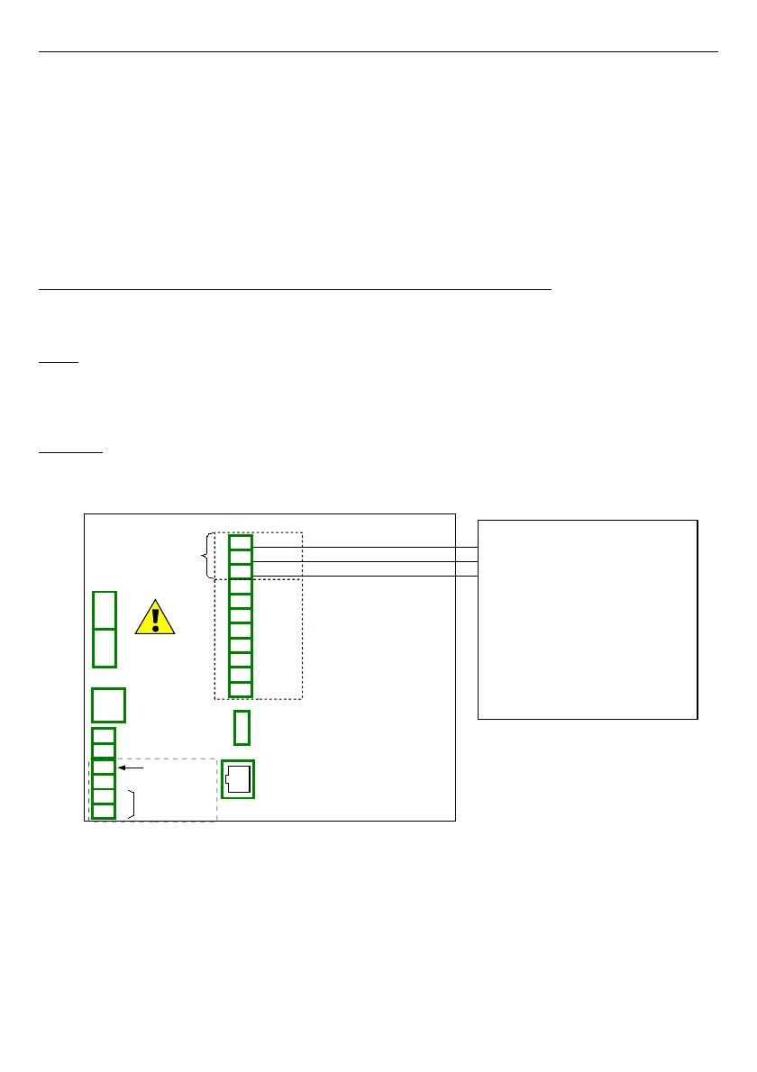
connect the device according to
Fig. 7.130
.
Fig. 7.130. Connection diagram for the Modbus port MB2
16-bits Slave device registers description is shown if
Tab. 7.10
.
220
19
16
17
18
14
15
RJ-45
ETH
USB host
RS-485 (2)
RxD
A+
B-
13
10
11
12
9
A+
B-
GND
TxD
CTS
RTS
RS-232 + RS-485 (3)
19
Slot D - ACM Module
Port MB2
GND
B-
A+
GND
GND
Power supply
(depending on version)
1
2
8
5
6
7
3
4
SERVICE
+24V DC ±5%
(
I
max. = 200mA)
digital input
0/15..24V DC
RS-485
GND
GND
A+
B-
isolated
Slave device 1
Slave address: 5
Register: 1h
Register: 2h
Register: 4h
Baud rate: 19200 bit./sek.
Device name:Flowmeter
Registers:
Modbus settings:
Register: 8h