User Manual For - CONTROLLER/DATA RECORDER MultiCon CMC-99/141
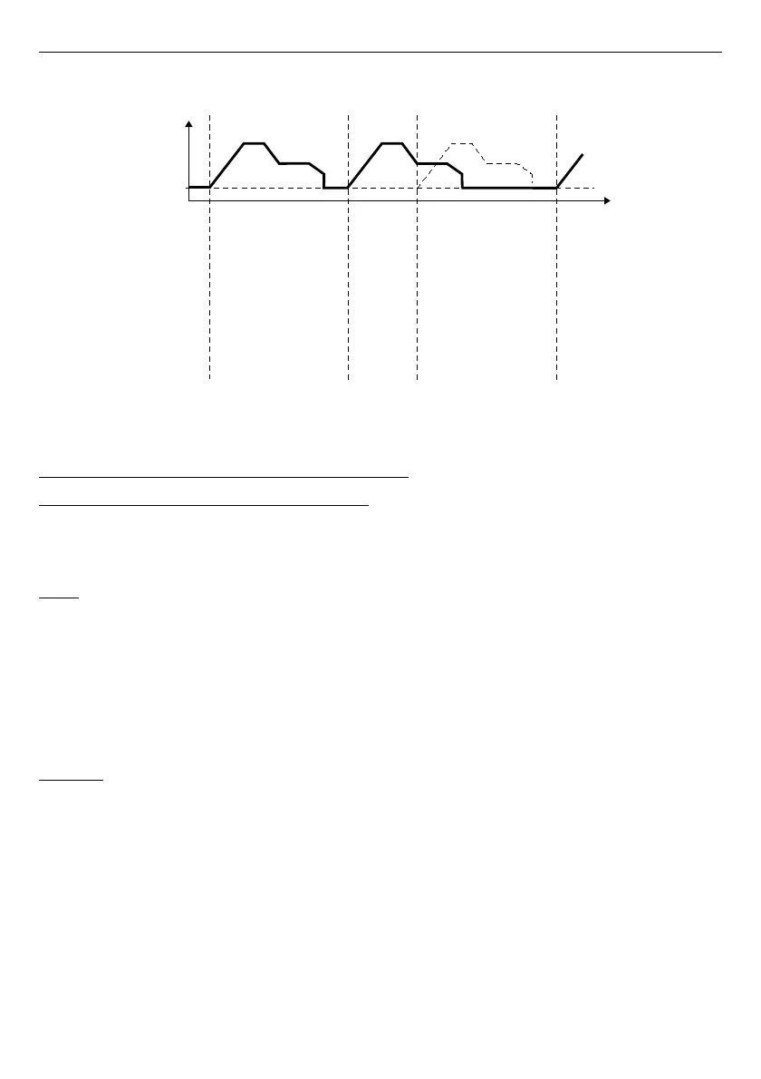
Fig. 7.105. Waveform for 'on time' triggering mode and time parameters in accordance
with Fig. 7.104
7.12.4. Examples of Profile/timer configuration s
7.12.4.1.
Application of the Profiles/timers
See also:
Chapter 7.12.2. Profiles/timers - Triggering mode: level (gate), edge (once),
edge (retrig.)
.
Task:
The task is to create a Profile timer in logical channel 1 in
edge (once)
mode, which
source is logical channel 2 which is connected to current input of
UI4
module. Profile consists
of four segments:
1. ramp from 0 to 10 during 5 seconds,
2. const.value 8 during 2 seconds,
3. ramp from 8 to 4 during 3 seconds,
4. const.value 4 during 1 second,
Looping is disabled and idle value is 0.
Solution:
First configure the device as described below, then connect the module to the
measuring system. Example of this connection is shown in
Fig. 7.57
(see also
Appendices
8.2. UI4, UI8, UI12, U16, U24, I16, I24 – VOLTAGE and CURRENT MEASUREMENT
MODULES
).
182
June 4 (Thursday)
14:42:00
July 4 (Thursday)
14:42:30
July 4 (Thursday)
14:42:20
July 4 (Thursday)
14:42:50
On time
Idle value
Time [s]
Output
value