User Manual For - CONTROLLER/DATA RECORDER MultiCon CMC-99/141
The answer:
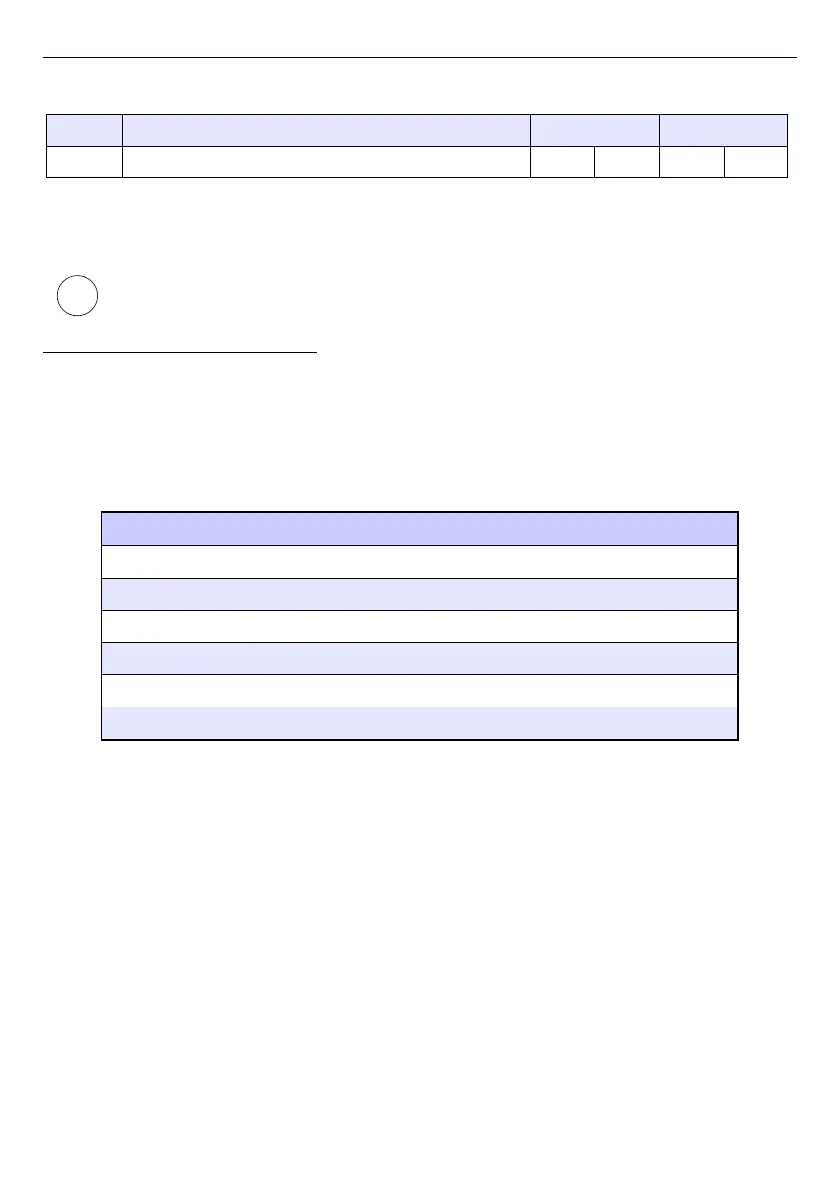
ADDR FUNC BYTE C DATA H1,L1 DATA H2,L2 DATA H3,L3 CRC L,H
01 03 06 00 0A 00 02 00 00 18 B4
DATA H1, L1 - 401h registry (10 – high word of value for channel 1, no decimal point),
DATA H2, L2 - 402h registry (2 – low word of value for channel 1, no decimal point),
DATA H3, L3 - 403h registry (0 – status for channel 1).
There is no full implementation of the Modbus Protocol in the device. The functions
presented above are the only available.
7.15.3. Modbus - MASTER mode
The parameters of a
Modbus
protocol for
MASTER
mode are:
–
Mode
=
MASTER
,
–
Baud rate
- this parameter allows the user to select baud rate RS-485 interface,
available option:
1200
,
2400
,
4800
,
9600
,
19200
,
38400
,
57600
,
115200
bit./sec.,
–
Format
- data format of the RS-485 interface, available options are shown in the
Tab. 7.8
.
Format Number of data bits parity control Number of stop bits
8N1
8 none 1
8N2
8 none 2
8E1
8 even 1
8E2
8 even 2
8O1
8 odd 1
8O2
8 odd 2
Tab. 7.8 Data format of the RS-485 interface
–
Request timeout
- is the amount of time (any value between 0.01 to 3 sec.) the
Master device waits for a response from the Slave device after sending a query,
–
Request retrials
- this is the number of times (integer value between 1 to 5) a
Master device tries to send a message,
–
Interval
– minimal amount of time that elapses between read/write cycles. The
read/write cycle contains all operations with Slave devices. If the Master device
requests all Slave devices in shorter time than the interval, then new requests will
begin after Interval elapses.
–
Slave device
- this Button enters submenu allows to define the list of Slave devices
connected to the current serial port of MultiCon and configure registers for read
and/or write. See below for more informations about this menu.
210
i