User Manual For - CONTROLLER/DATA RECORDER MultiCon CMC-99/141
7.8.11.10. Application of Logical channel in the Hardware input mode and Data from
other channel for FT4 module
See also: Chapter 8.5. FI2. FI4, FT2, FT4 – FLOWMETER MODULES.
Task:
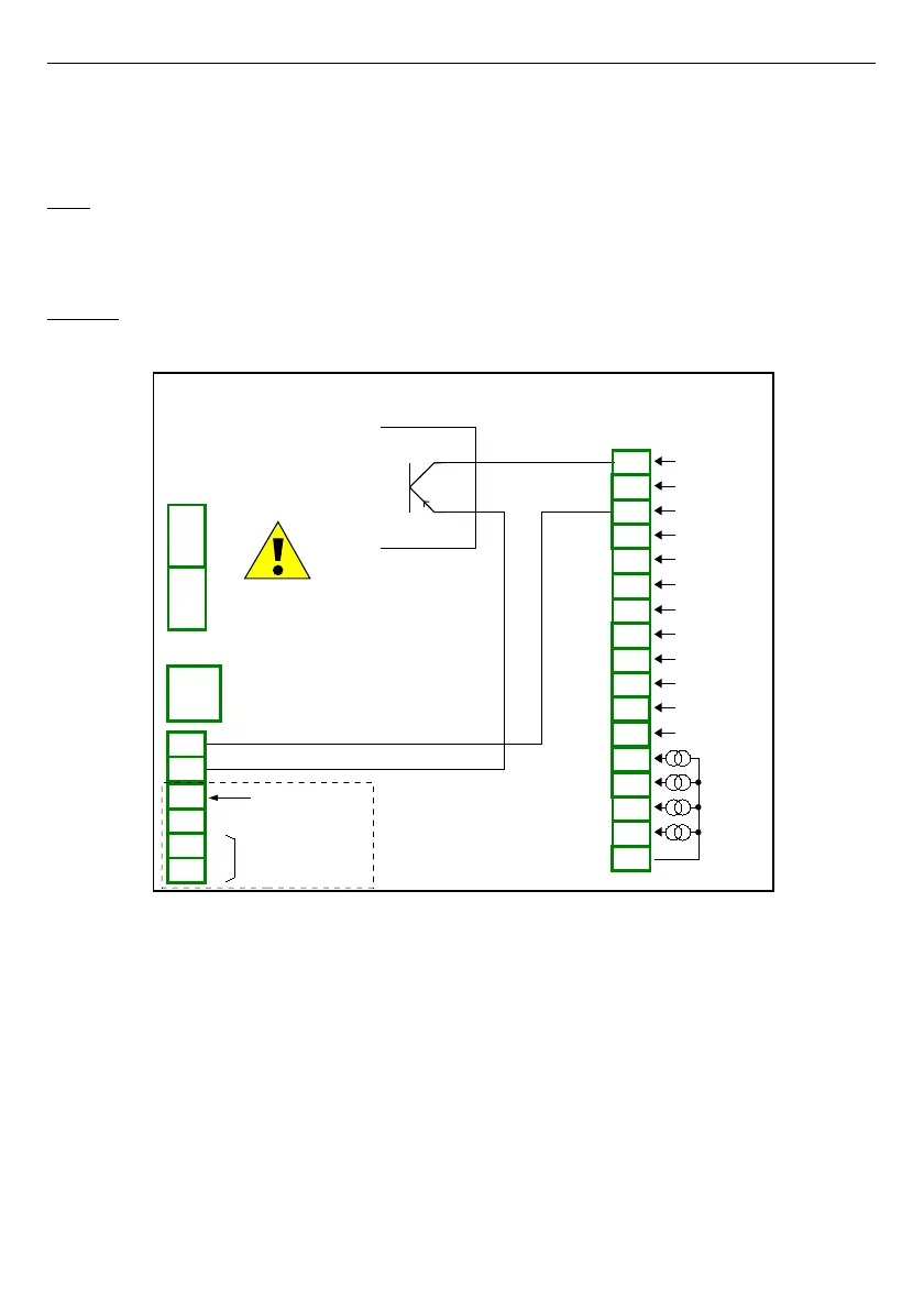
The task is to connect sensor PNP type, read measurement from FT4 Flowmeter
hardware input and to display current
Flow
and
Total flow
. Sensor gives 512 pulses per liter
of liquid.
Solution:
Before configuring the device according to
Fig. 7.74
, configure the device as it is shown
bellow.
Fig. 7.74. FT4 module and PNP type sensor connection scheme
For logical channel in
Hardware input
mode:
– touch screen and press the
Menu
button,
– press the
Device configuration
button,
– enter
Logical channels
menu,
– using the arrows in the top navigation bar, select any
logical channel
, in this
example we it will be channel 1,
• in
Name
parameter write
Measurement
,
•
Mode
parameter set as
Hardware input
,
•
Source
parameter set as
Inp.A1 : Tacho
,
• press
Configure source
button,
◦ in
Base unit
parameter write
dm
3
,
◦
Mode
parameter set as
Flow/Tacho (1/sec.)
,
135
PNP
Power supply
(depending on version)
1
2
8
5
6
7
3
4
SERVICE
+24V DC ±5% (Imax. = 200mA)
digital input
0/15..24V DC
RS-485
GND
GND
A+
B-
isolated
FT4
4 pulse inputs
+ 4 current inputs
n15
n16
n17
n04
n05
n13
n14
n01
n02
n03
n04
n05
n01
n02
n03
n06
n10
n11
n07
n08
n09
n12
GND
IN5
IN6
IN7
IN8
4 x 0-20mA
COM4
Inp42
Inp41
COM3
Inp32
Inp31
COM2
Inp22
Inp21
COM1
Inp12
Inp11