User Manual For - CONTROLLER/DATA RECORDER MultiCon CMC-99/141
7.8.11.6. Application of Logical channel in the Hardware input for TC8 modules
See also: Appendices 8.6. TC4, TC8, TC12 – THERMOCOUPLE SENSOR
MEASUREMENT MODULES and Chapter 7.8.6. Logical Channels - Math function mode.
Task:
In this example we calculate the mean value from logic channels 1÷8. In these channels
are values from thermocouple sensors that are located around the furnace.
Solution:
Before measuring temperature, user should configure the device as follows and then
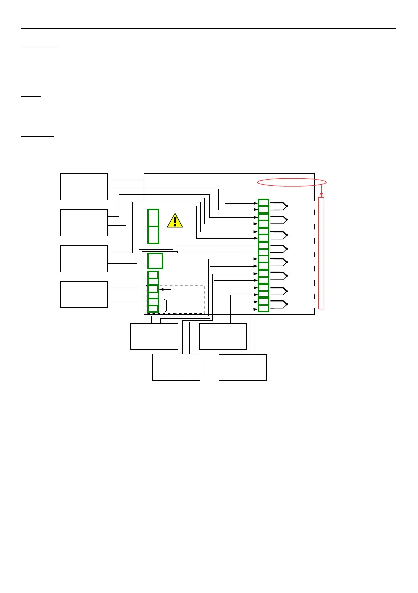
connect the thermocouple sensors to the device. An example of the connection is shown in
Fig. 7.70
.
Fig. 7.70. Schematic diagram for the TC8 module
To configure logical channels for reading temperatures from 1÷8 inputs (names
Temperature 1
,
Temperature 2
, etc.) should follow the same way as in
7.8.11.2.
Application of Logical channel in the Hardware input mode for TC4 modules
.
For Logical channel in
Math function
mode calculated an average value:
– touch screen and press the
Menu
button,
– press the
Device configuration
button,
– enter
Logical channels
menu,
– using the arrows in the top navigation bar, select any
logical channel
(except 1÷8)
such as
9
,
– in Name parameter write
Mean value
,
– Mode parameter set as
Math function
,
– enter
Function
submenu to select the appropriate function that allows the
calculation of the mean value,
127
Power supply
(depending on version)
1
2
8
5
6
7
3
4
SERVICE
+24V DC ±5%
(
I
max. = 200mA)
digital input
0/15..24V DC
RS-485
GND
GN D
A+
B-
isolated
TC4
4 thermocouple input
IN1
+
-
IN2
+
-
IN3
+
-
IN4
+
-
n01
n02
n03
n04
n05
n06
n07
n08
1
5
6
7
4
2
Slot A
IN6
+
-
IN7
+
-
IN8
+
-
n09
n10
n11
n12
n13
n14
n15
n16
3
8
Inp.A1 : Thermocouple
Inp.A2 : Thermocouple
Inp.A3 : Thermocouple
Inp.A4 : Thermocouple
Inp.A5 : Thermocouple
Inp.A6 : Thermocouple
Inp.A7 : Thermocouple
Inp.A8 : Thermocouple
IN5
-
+