User Manual For - CONTROLLER/DATA RECORDER MultiCon CMC-99/141
7.11.4. Examples of external output configuration s
During the
External output
configuration, user should terminate communication
between the MultiCon and the SLAVE device.
7.11.4.1.
A pplication of external output for protocol Modbus in the MASTER mode
See also: Chapter 7.15.3. Modbus - MASTER mode.
Task:
The task is to send data located in Logical channel 1 to SLAVE device (address 5)
without scaling and restrictions.
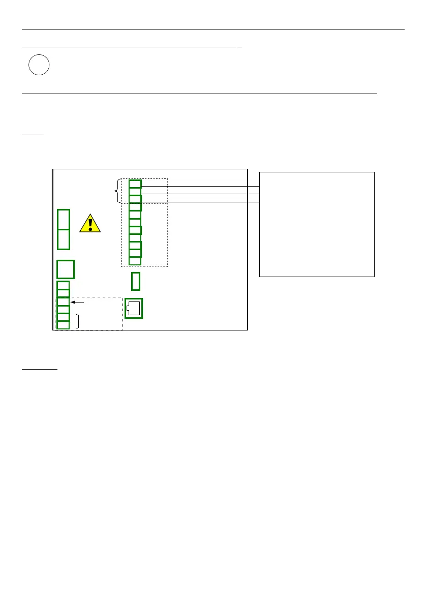
Fig. 7.97. Connection diagram for Modbus MB2
Solution:
First we need to configure settings in Modbus menu as it is shown in
7.15.4.2.
Configuration of the Modbus Input in the MASTER mode.
. Next:
We configure logical channels used to set values, which will be send by RS-485 to the output.
To do this:
– touch screen and press the
Menu
button,
– press the
Device configuration
button,
– enter the
Logical channels
menu,
– using the arrows in the top navigation bar, select any
Logical channel
such as 1,
– in
Name
parameter write
Set point value
,
–
Mode
parameter set as
Set point value
,
– in
Set point
value parameter write
50
,
– for
Displaying
block parameters:
•
Format
parameter set as
numeric
,
•
Precision
parameter set as
0
,
• in
Graph low
parameter write
0
,
• in
Graph high
parameter write
65535
,
171
i
19
16
17
18
14
15
RJ-45
ETH
US B host
RS-485 (2)
RxD
A+
B-
13
10
11
12
9
A+
B-
GND
TxD
CTS
RTS
RS-232 + RS-485 (3)
19
Slot D - ACM Module
Port MB2
GND
B-
A+
GND
GND
Power supply
(depending on version)
1
2
8
5
6
7
3
4
SERVICE
+24V DC ±5%
(
I
max. = 200mA)
digital input
0/15..24V DC
RS-485
GND
GND
A+
B-
isolated
Slave device 1
Slave address: 5
Register: 1h
Register: 2h
Register: 4h
Baud rate: 19200 bit./sek.
Device name:Flowmeter
Registers:
Modbus settings:
Register: 8h