User Manual For - CONTROLLER/DATA RECORDER MultiCon CMC-99/141
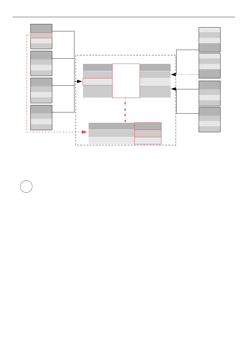
Fig. 7.48. An example of configuration block diagram of the Modbus protocol implemented in
the device
Logical channel's in Modbus mode reading registers from Slave devices that
are not connected, will returns an error and instead of the value will display the
state
-ERR-
.
For more information about the Modbus protocol implemented in the MultiCon see
Chapter
7.15. MODBUS
.
91
i
Port MB1
SLAVE Device Address 1
Device input
Register 0
SLAVE
Device
Reg. 0
...
Reg. N
SLAVE
Device
Reg. 0
...
Reg. N
SLAVE
Device
Reg. 0
...
Reg. N
SLAVE
Device
Reg. 0
...
Reg. N
Address 1
Address 2
Address 52
Address 82
SLAVE
Device
Reg. 0
...
Reg. N
SLAVE
Device
Reg. 0
...
Reg. N
Reg. N
...
Reg. 0
SLAVE
Device
Address 82
Address 8
Reg. N
...
Reg. 0
SLAVE
Device
Address 1
Address 4
Built-in
Modbus
Master
Advanced
Port MB2
Port MB1
Port MB3
Unit
Device configuration
Hardware Inputs
Modbus