5-2
Chapter 5 Specifying Hardware Components
Specifying Hardware Components
Hardware Tab
Overview
Table 5-1 lists the available hardware icons and their descriptions.
Adding Hardware There are two ways to add a hardware component to the programmer:
• Drag and drop
• Right click + add
To add a hardware component to the programmer using drag and drop:
1. Locate the hardware component that you want to add from the Available Hardware window
on the right of the programmer screen.
2. Click on the hardware and drag it into the Hardware Configuration window on the left of the
programmer screen, into the proper directory:
• Units must be placed in panel icons.
• Boxes must be placed in units.
• Cards must be placed in boxes.
3. When the component is in the proper place, release the mouse. If the component was
successfully added, it appears in the Hardware Configuration menu. If the component
cannot be added to the configuration, an error message appears with the problem diagnosis.
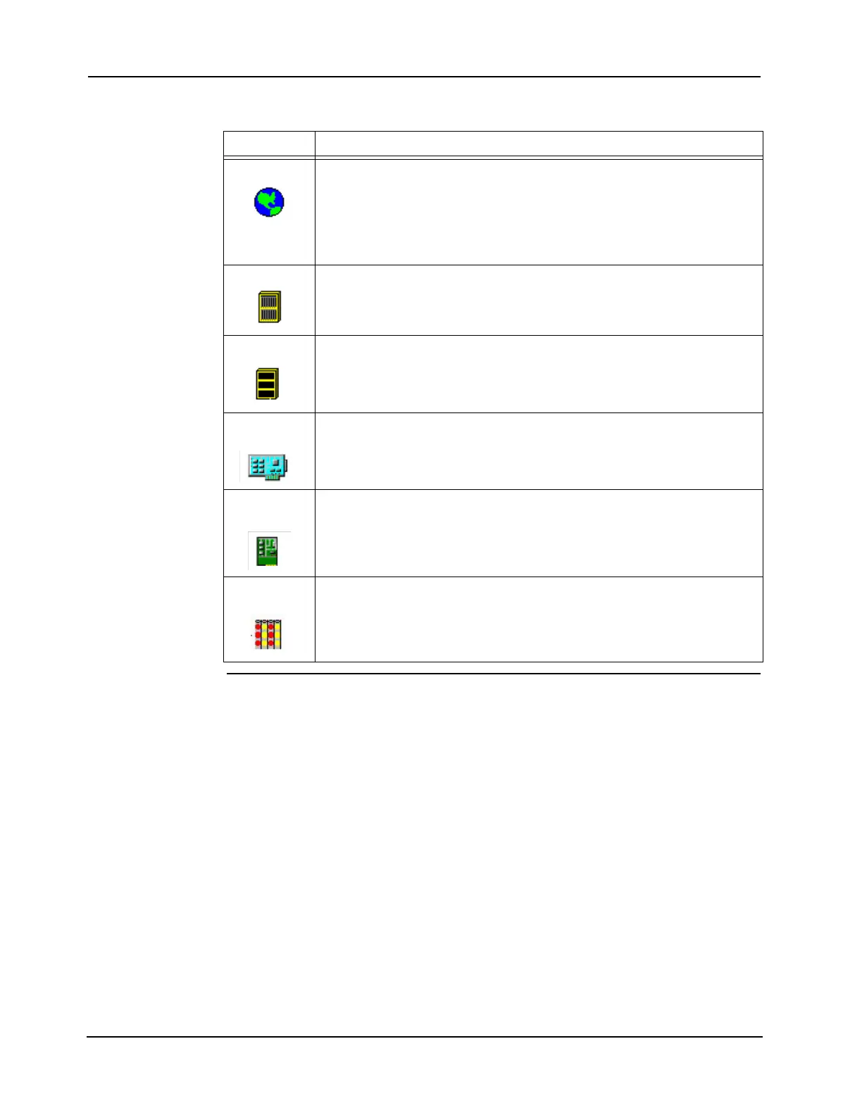
Table 5-1. Hardware Tab Icons
Icon Meaning
Panel Icon This icon permanently resides in the top left corner of the work area. The panel
icon represents all of the non-networked, RUI-linked components controlled by
a single CPU. A single panel may, for example, actually be multiple boxes,
some residing at one location and some at another location.
Highlighting this icon and hitting Shift-Right Arrow at the same time expands
the entire hardware tree.
Unit Icon The unit icon does not represent actual equipment. It corresponds to a location
at which the box resides.
Click on the + sign to expand the contents of a unit and see the box.
Box Icon The box icon typically represents a standard bay box. There is also an option
that represents a custom box.
Click on the + sign to expand the contents of the box.
Logical Card
Icon
Logical cards are not hardware; instead they represent all of the analog pseudo
points, digital pseudo points, or lists used on the system.
Double click on the card to access its properties.
Physical
Card Icon
Physical cards are actual hardware, including: monitor, signal, relay,
annunciator, display, interface, and power cards.
Double click on the card to access its properties.
LED Module
Icon
This icon represents the fixed-48 LED Module. The module is installed directly
in a recess of the dress panel.
Double click on the card to access its properties.