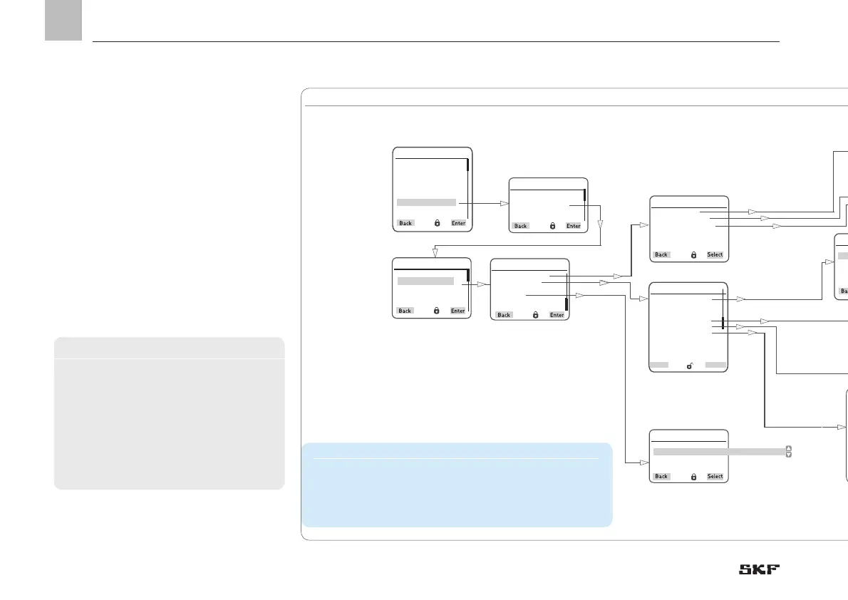
EasyManuals Logo

SKF LMC 301 series User Manual

SKF LMC 301 series
154 pages
To Next Page IconTo Next Page
To Previous Page IconTo Previous Page
Page #102 background imageLoading...
Page #102 background image
11. System configuration
Lube Control
Valve A
Press. Sensor at EOL
Lube Control Time
Sensors
Zurück
Wählen
Login settings
User settings
Device settings
Pump 1 Timings
System configuration
Informationen
Main Menu
System configuration
Amount of pumps
Pump 1settings
Set Params to Default
Restore Fact. Set
Pump 1 settings
Pump settings
Zone 1 Settings
Zone 2 Settings
Zone 1 Settings
Cycle Control
Lube Control
Alarm
Cycle Control
Timings
Release/Counter
Lube Load
Output Type
[ << normally open> <<normally closed >> << disabled>>
Output No.
[ 1,04
Alarm
Ausgangstyp
[ << nomally open >> << normally closed >> << dsabled>> ]
Output No.
[ 1,06 ] 0
11.2.5 MA/MP per Zone
Application-specific nomenclature
EOL End of the main line
Reversing valve Hydraulic reversing valve
Proximity sensor For stroke monitoring
The model MP2 pneumatically actuated
change-over valve with the model WS-P2
pneumatically actuated directional spool
valve corresponds largely to the principle of
the pneumatically actuated 4/2 directional
control valve, which supplies the lubricant
fed by the pump into one of the two main
lines while the other main line is connected
to the return flow connection of the pump.
Instructions
Model MP2 pneumatically actuated
change-over valve and model WS-P2
pneumatically actuated directional spool
valve
Document No. 1.3G-48001-C07
1.3G-58001-B02
EN
102

Table of Contents

Other manuals for SKF LMC 301 series

Questions and Answers:

Question and Answer IconNeed help?

Do you have a question about the SKF LMC 301 series and is the answer not in the manual?

SKF LMC 301 series Specifications

General IconGeneral
BrandSKF
ModelLMC 301 series
CategoryController
LanguageEnglish

Related product manuals