) see Figure 8, item 1, and Fig. 11
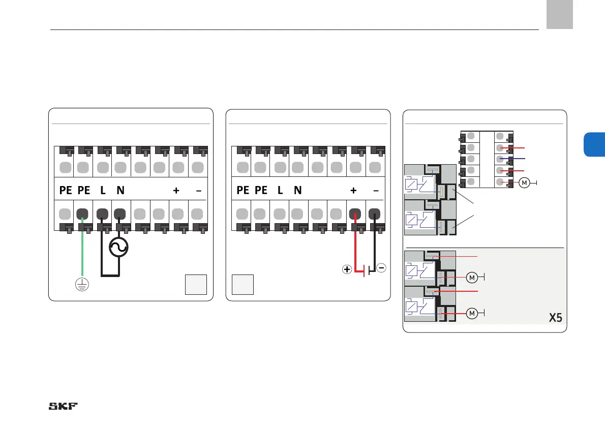
Terminal diagram 24 VDC, Fig. 12
• Connect customer-provided cable for
power supply acc. to terminal diagram 24
VDC, Fig. 10
• Connect customer-provided cable for
power supply acc. to terminal diagram
100 to 240 VAC, Fig. 11
)The 24 VDC is generated internally. Do
not connect externally generated 24
VDC to terminal (+) or terminal (-).
5.3.7 Load switching relay
) see Figures 8/9, item 11, and Figure 13
Example of load switching relay, Fig. 13
• Connect (loop) customer-provided load
voltage cable to both terminals of the load
relay.
) see Figure 9, item 1, and Fig. 12
O 3
O 2
O 2
O 1
O 1
Input 230 VAC
max. 8 Ampere
Input 230 VAC
max. 8 Ampere
M
Output
max. 8 Ampere
M
Input 230 VAC, max. 15 Ampere
Input 24 VDC, max. 15 Ampere
Input 230 VAC,
max. 15 Ampere
Input 24 VDC,
max. 15 Ampere
M
Relay 2
Relay 1
Connection up to
max. 8 amperes
Load relay con-
trolled directly

 Loading...


