5.2.2 Opening the controller unit
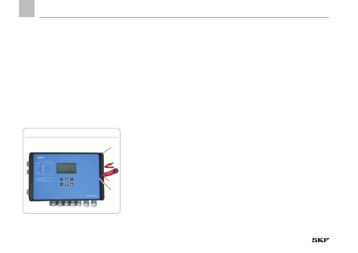
Opening the controller unit, Fig. 7
• Insert a flat tip screwdriver (1) with a
maximum blade width of 5.5 mm into the
opening slot (2)
• Tilt the screwdriver (1) slightly to the right
to open the cover (3)
)Open the cover by briefly clicking and then
opening the cover by hand.
) see Figure 6 and Fig. 7
5.2.3 Minimum mounting dimensions
To ensure enough space for maintenance
work and possible disassembly of the
product, ensure that the minimum
mounting dimensions (Fig. 6) are
maintained.
5.2.4 Assembly of the controller unit
) See Figure 6
The controller unit is installed using 4
cheese-head screws of thread size M4.
If M4 tapped bores are used to fasten the
unit, the screws must have a minimum
length of 15 mm.
Fastening material to be provided by the
customer:
o Cheese-head screws with hexagon socket
(4x) acc. to DIN6912-M4x.. -8.8
o Washers (4x) acc to.
DIN EN ISO 7090-4-200HV
o Self-locking nuts M4 (4x) acc. to
DIN EN ISO 10511; drill assembly holes
(Ø 4.3 mm) acc. to assembly drawing
(Fig. 4) and the conditions on the surface.
• Clean surface to remove drilling chips.
• Open the controller unit, place it on the
surface, and roughly align it
• Pass cheese-head screws (4x) through
the fixing holes on the controller unit and
the mounting surface
• Apply washers to cheese-head screws,
gently tighten cheese-head screws.
• Align the controller unit, tighten cheese-
head screws
Tightening torque 4 Nm
1
2
3

 Loading...


