5. Assembly
EN
34
) see Figures 8 and 9
5.3.4 Line routing
The lines are laid through cable glands
attached on both sides and on the bottom
The attached cable glands are provided for
the following lines:
Cable glands on left side:
o Power supply
o Master/slave connection
Cable glands on right side:
o Relay outlets (load-dependent)
o Pump motor
Cable glands on bottom:
o Inputs and outputs for monitoring units
(sensors)
• Loosen the cable gland
• Draw the connection cable (provided by
customer) into the cable gland
• Connect the connection cable (provided by
customer)
according to the wiring diagrams (see
Figs. 11 to 18)
• Tighten the cable gland
) See Figures 8 and 9
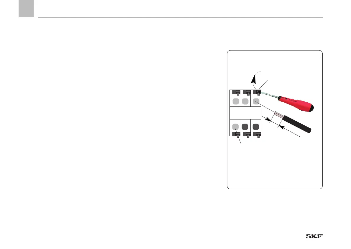
and Fig. 10
The wires on the terminal strips for:
o Power connection (item 1)
o Digital outputs (item 2)
o Analog outputs (item 3)
o Relay (item 4)
are connected via a tension spring mecha-
nism. Proceed as follows:
• Press the tension spring back using the
flat tip screwdriver
• Insert flexible cable leads into the
terminals
• Release pressure on the tension spring
• Check that the wires are securely
connected
5.3.5 Connecting wires
Fig. 10
 Loading...


