5. Assembly
EN
37
5
)See Figures 8/9, item 2, and Figure 16
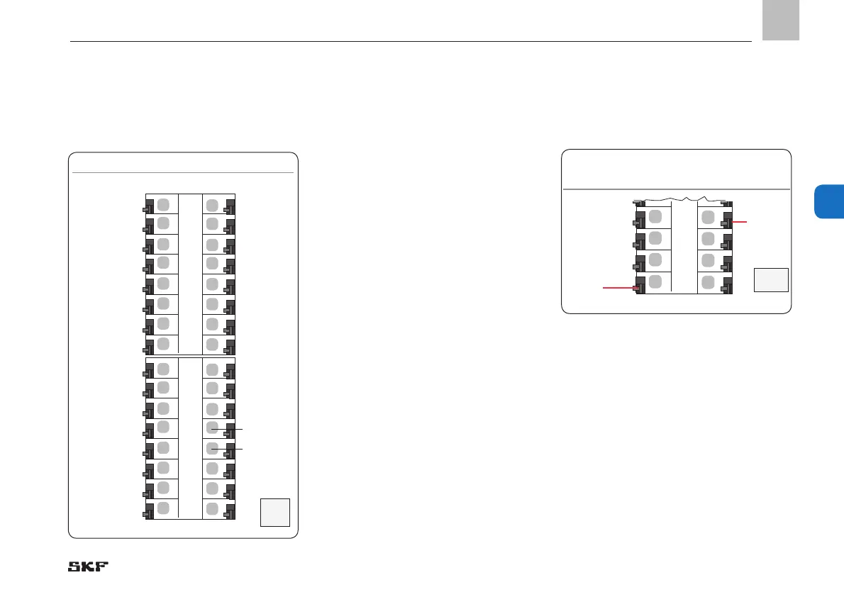
5.3.9 Terminal strip for digital inputs
Terminal strip for digital inputs, Fig. 16
+
I 3
I 4
-
+
I 5
I 6
_
+
I 7
I 8
-
+
I 9
I10
_
I = Input
The digital inputs are provided for:
o Pressure switch
o Proximity switch
o Flow sensor
o Fill level switch
o Interim lubrication switch
• On the digital switch, attach power supply
(+) to plus terminal (+)
• On the digital switch, attach ground
connection (-) to minus terminal (-)
• On the digital switch, attach signal line
for digital switch to corresponding input
terminal (I3 to I10)
1) No grounding connection (minus) is supported for
two-wire sensor designs (plus + signal).
5.3.10 Terminal strip for analog-capable
inputs
Terminal strip for analog-capable inputs,
Fig. 17
+
I 1
I 2
_
I = Input
The analog-capable inputs are provided for:
o Pressure transducer
o Temperature switch
o Switch polled in mA or volt, e.g.,
4-20 mA, 1-6 volt
• On the analog switch, attach power
supply (+) to plus terminal (+)
• On the analog switch, attach ground
connection (-) to minus terminal (-)
• On the analog switch, attach signal line to
corresponding input terminal (I1 /I2)
)See Figures 7/8, item 3, and Figure 17
X2
X3
Plus
Minus
1
)
Plus
Minus

 Loading...


