6. Configuration by operator/local admin
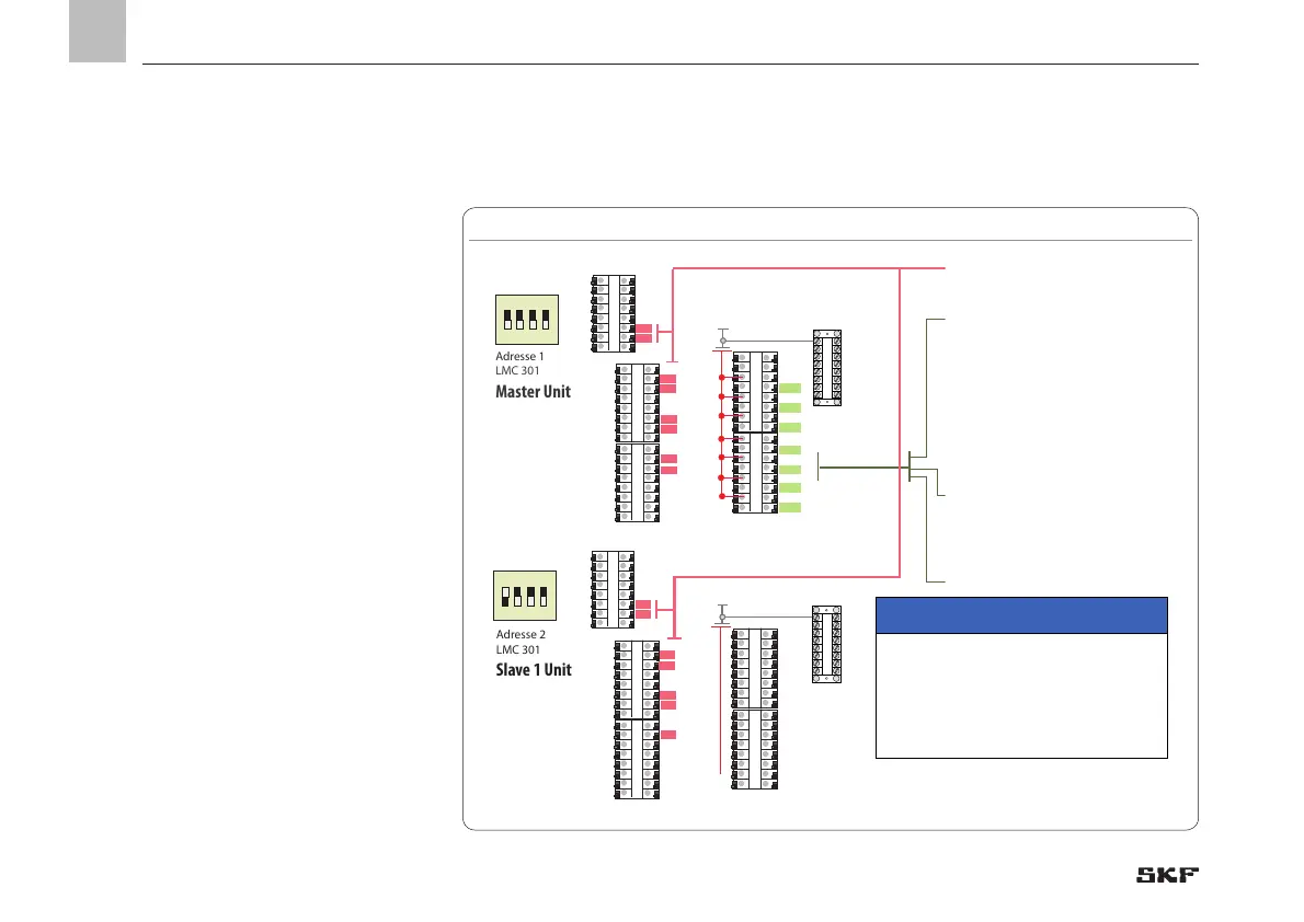
LMC 301, electrical terminal diagram, Fig. 27
)See Figure 27 and Fig. 28
6.4.2 2-zone Dual Line centralized lubrication system with EMU3 and 2 pressure switches
ON
1 2 3 4
I 1.1
I 1.2
I 1.3
I 1.4
I 1.5
I 1.6
I 1.7
I 1.8
I 2.1
I 2.2
I 2.3
I 2.4
I 2.5
I 2.6
I 2.7
Ø1
Ø2
Ø3
Ø4
Ø5
Ø6
Ø7
Design
The example applies to a Dual Line centralized
lubrication system with two zones (zone 1/
zone 2 (line 1/line 2)).
It is composed of the main components
Dual Line pump (1) with pressure-regulat-
ing valve (2), two electrical 4/3 zone valves
(5/6) (EMO3), and Dual Line feeders (13).
A main line (3) with a pressure switch (4) is
flanged to the pump and switches off the
pump once the set maximum pressure is
reached. The main line (3) connects the
pump outlet with the two electrical 4/3 re-
versing valves for zone 1 (5) and zone 2 (6).
A PT pressure switch (7 to 10) for pressure
monitoring (change-over pressure) is fit-
ted at the end of each line ahead of the last
feeder. Further, a piston detector is fitted on
the last feeders (11/12) to monitor the lu-
brication cycles. Chapter 3 contains a
general functional description.
IMPORTANT NOTE
Only one operating voltage (24 VDC or 230
VAC) can be connected to terminal strip 4.1
or 4.2. Do not operate two different voltages
within a terminal strip!
EN
70
 Loading...


