RESET
LMC 301
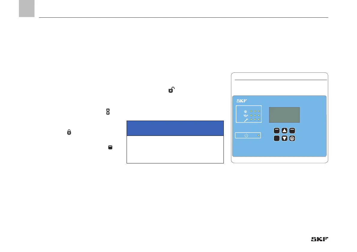
6.3.2 Display and control elements of
the control screen 6.3.1 Overview States
After switching on the supply voltage, the
Overview States menu appears on the
display.
The current parameter settings and values
are displayed. This is done continuously and
automatically.
The parameters and settings can optionally
be accessed using the two arrow keys
No entries can be made and the symbol
shows a closed lock
.
To change the configuration, select the
menu item Menu using the control key
.
This will take you to the Main menu.
Changes can be made within the main menu
only after entering the password. This is
done in the Login settings menu level.
When entering the password, there is a dif-
ferentiation between Local Admin (customer
access) and Supervisor (only service staff, no
customer access).
The open lock icon
indicates that the
system has been unlocked.
IMPORTANT NOTE
To save data, press the Save control key for
at least 3 seconds.
EN
42
6.3 Configuration of the controller unit via the display on the controller unit

 Loading...


