6. Configuration by operator/local admin
6.2 System mode half cycle
In a half cycle, the controller enters runtime
1 after the defined interval time. After run-
time 1 elapses and the changeover signal
is received, pressure is relieved in the pres-
surized main feed line (1 or 2). At the same
time, the control unit enters interval time.
Runtime 2 follows after pressure is relieved
and the interval time elapses. After runtime
2 elapses and the changeover signal is
received, pressure is relieved in the pres-
surized main feed line (1 or 2). At the same
time, the control unit enters interval time.
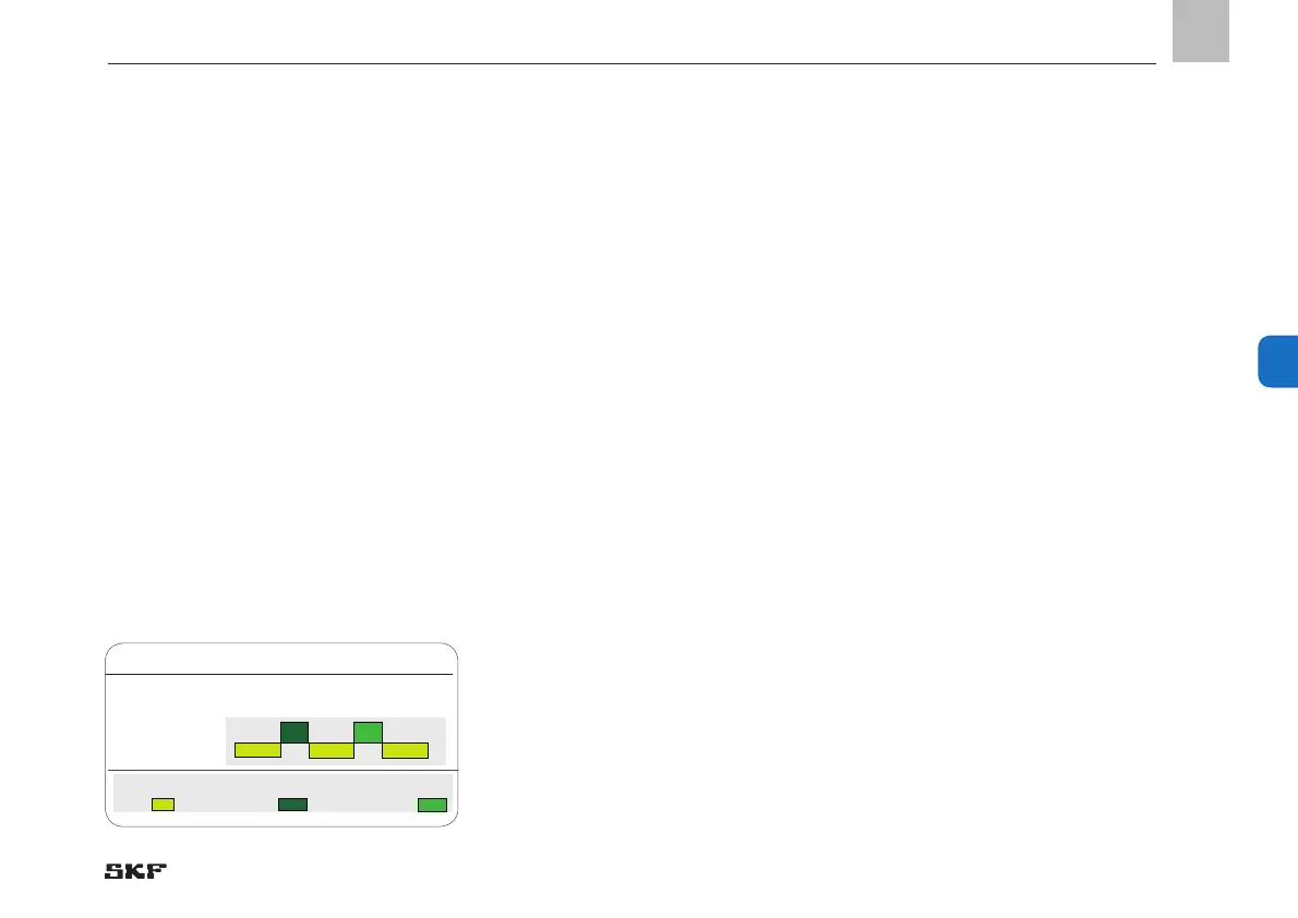
A complete lubrication cycle consisting of
two half-cycles, separated by an interval
time, is thus completed.
Half cycle, Fig. 22
Halbzyklus:
Legende
Pause:
Running time (1) Running time (2)
6.2.1 Pressure sensor EOL
Various sensors can be used to record the
system pressure at the end of the main
lines. In addition to sensors with NC contacts
or NO-contacts, transducer sensors whose
response is in the volt or mA areas are
generally used. With all these versions, the
respective inputs for line 1 and line 2 must
be defined.
The following applies additionally to the
transducer versions:
To define the measurement range, enter
their specific measurement ranges <<Mini-
mal Value>> / <<Maximal Valve>>.
Defining the pressure range permissible
for the particular system requires entry of
the << Min. Absolute Pressure>> and the
<<Maximal Absolute Pressure>>.
Defining the permissible pressure difference
between line 1 and line 2 requires entry of
the << Min. Differential Pressure>> and the
<<Maximal Differential Pressure>>
Make the settings on both transducers (for
line 1 and line 2) immediately.
Based on the permissible measurement
range, the two transducers will measure the
pressure present at line 1 and line 2 and
forward this to the LMC 301. The Controller
monitors pressure reduction on the relieved
line and the pressure build-up of the actu-
ated line. At the same time, the Controller
compares the values with the entries for
permissible differential pressure. When the
desired differential pressure
<< Min. Differential Pressure>> and
<< Min. Absolute Pressure>> is reached,
the Controller enters interval time and
switches off the pump.
EN
41
6

 Loading...


