11. System configuration
11.6.2 Zone 1 Settings with EM U3
)See illustration of zones in Chapter 11.2.2
Pump settings => Zone 1 Settings => Lube Control
Step Key Display Description
Zone 1 Settings/Lube Control Settings with EM U3 valves A/B/C
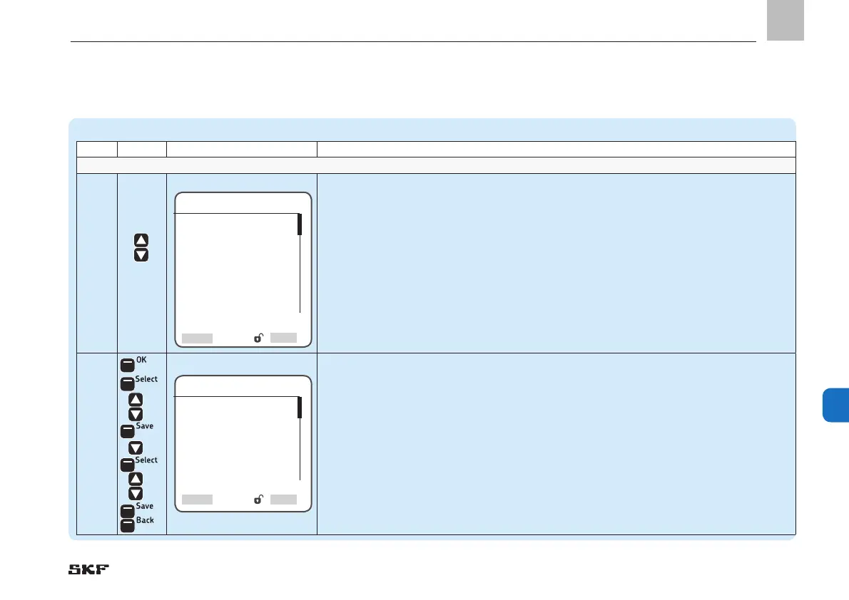
1
• Use <down/up arrow key> to select the Lube Control menu
• Press <OK control key>
)You will enter the Lube Control menu
)The following settings are available:
o Valve A (valve position A) / pos. Valve A Step 1.1 / 1.4
o Valve B (valve position B) / pos. Valve B Step 1.2 / 1.5
o Valve M (valve position M) / pos. Valve M Step 1.3/ 1.6
o Press. Sensor at EOL Step 1.7
o Main Line Timings Step 1.8
o Proximity Sensor Step 1.9
1.1
• Use <OK arrow key> to select valve A (activate valve position A)
• Press <Select control key>
• Use <down/up arrow key> to select between menu items normally open, normally
closed, or disabled
• Press <Save control key>
• Use <down arrow key> to select the Output No. menu item
• Press <Select control key>
• Use <down/up arrow key> to enter the output No.
• Press <Save control key>
• Press <Back control key>
Lube Control
Valve A
Valve B
Valve M
Pos. valve A
Pos. valve B
Pos. valve M
Press. Sensor at EOL
Main Line Timings
Proximity Sensor
Valve A
Output Type
[<<normally open>><<normally
closed>>
<<disabled>>]
Output No.
[0.000]
Select

 Loading...


