2. Overview/System description
)See Figure 3
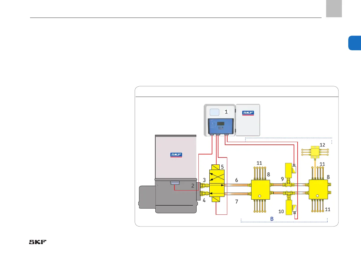
The following description applies to a 230
VAC Dual Line centralized
lubrication system for industrial use with
one main line. Control unit LMC 301 (1) is
installed in a control cabinet, with load unit
and power supply for the pump motor and
for the attached valves and sensors.
One grease supply line (3) and one grease
return line (4) are flanged to the pump
housing (2) of the Dual Line pump. These
are flanged with their respective ends to an
electrical changeover valve (5).
Two main feed lines (6) (7) proceed from the
electrical changeover valve to the Dual Line
distributors in downstream alignment (8).
An analog pressure sensor (9) (10) has been
fitted ahead of each of the last Dual Line
distributors of main feed line 1 (A) and main
feed line 2 (B). The sensor transmits a signal
corresponding to the existing pressure to
the control unit (the control units compares
the two signals). Fill level monitoring is
performed by a fill level switch located in
the pump reservoir. This switches the pump
2.2 General design of a Dual Line centralized lubrication system with one main line with two analog pressure sensors
off when the minimum fill level has been
reached.
Example of a Dual Line Dual Line centralized lubrication system with one main line, Fig. 3
A
EN
19
2

 Loading...


