IMPORTANT NOTE
Only one operating voltage (24 VDC or 100-240 VAC) can be connected to terminal strip
4.1 or 4.2. Do not operate two different voltages within a terminal strip!
EN
32
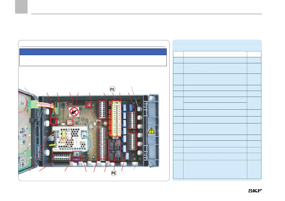
5.3.2 Terminal board 100-240 VAC
Connections on mainboard, design 100-240 VAC, Fig. 8 Legend to Figure 8
Item Description Chapter
1 Power supply X1
5.3.6
1a
Internal 100-240 VAC connection
for the AC/DC power supply unit
1b
Internal 24 VDC connection from AC/
DC power supply unit to the board
2 Digital inputs X2
5.3.9
3 Digital/analog inputs X3
5.3.10
4
4.1 Relay outputs X4
5.3.8
4.2 Relay outputs X4
5
RS485 interface
6
24 VDC output for mainboard
7
USB port (external)
Do not use connection!
8
DIP switch addresses 5.3.11
9
RESET switch Hardware reset
10
Fuse,
FK1 3A as per ISO 8820-3
11 Load switching relay (2x) X5
5.3.7
12
PE/ground terminals
for relay outputs. X6
Grounding connection
established by customer!
5.3.8
 Loading...


