11. System configuration
Pump settings => Pump settings => Lube Control => Sensor at Pump Set.
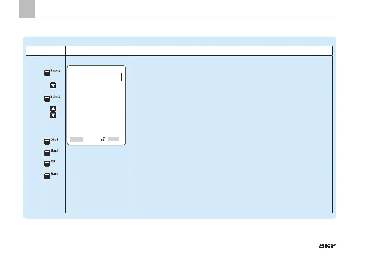
Step Key Display Description
3.3
With transducer:
• Press <Select arrow key>
• Select transducer type [transducer 1-6 V] [transducer 4-20 mA] [transducer 0-20 mA]
[transducer 2-10 V]
• Press <down arrow key>
The following settings are available:
o Input - the first or second input is configurable as an analog value (AI)
)Entering the output No. specifies the controller terminal of the pump sensor. DI stands
for digital input, and AI stands for analog input.
o Minimal Value - entry of the minimum permissible system pressure (in PSI) of the
pump
o Maximal Value - entry of the maximum permissible system pressure (in PSI) of the
pump
o Operating Pressure - Entry of the operating pressure for switching pump on/off (in PSI)
• Press <Select control key>
• Use <down/up arrow key> to enter the respective values
• Press <Save control key>
• Press <Back control key>
• Press <OK control key>
• Press <Back control key>
 Loading...


