2. Overview/System description
Display and control elements of control screen
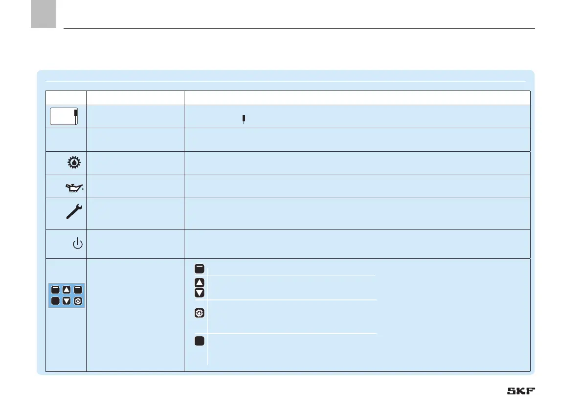
Symbol Designation Function
Display o Menu display/Display of values and parameters/Fault display
o The right bar (
) indicates that the menu extends beyond the current display
PUMP
PUMP
Pumps A B C
Pump/main line A / B / C per pump
Max. of 3 main lines possible
RUN
RUNning
Active control
LED lights up =
Indication of currently active pump/active control line (A/B/C)
LL
Low Level
Minimum fill level reached
LED lights up =
Minimum fill level (pump A / B / C) reached
FA U LT
FA U LT
Fault notification
o LED flashes = Fault detected
o LED lights up = Fault present
POWER POWER
Control unit On/Off
LED lights up = Control unit switched on
Function keys
Control key in combination with the display above the key
Up arrow key menu control <Back menu level> / increase input value
Down arrow key menu control <Forward menu level> / reduce input value
Pressing triggers an interim lubrication.
Briefly pressing selects an interim lubrication.
Actuations while in configuration mode are ignored.
RESET
Long pressing (> 3 seconds) stops all systems or resets error notifications.
Long pressing acknowledges and clears error notifications.
RESET
EN
16
 Loading...


