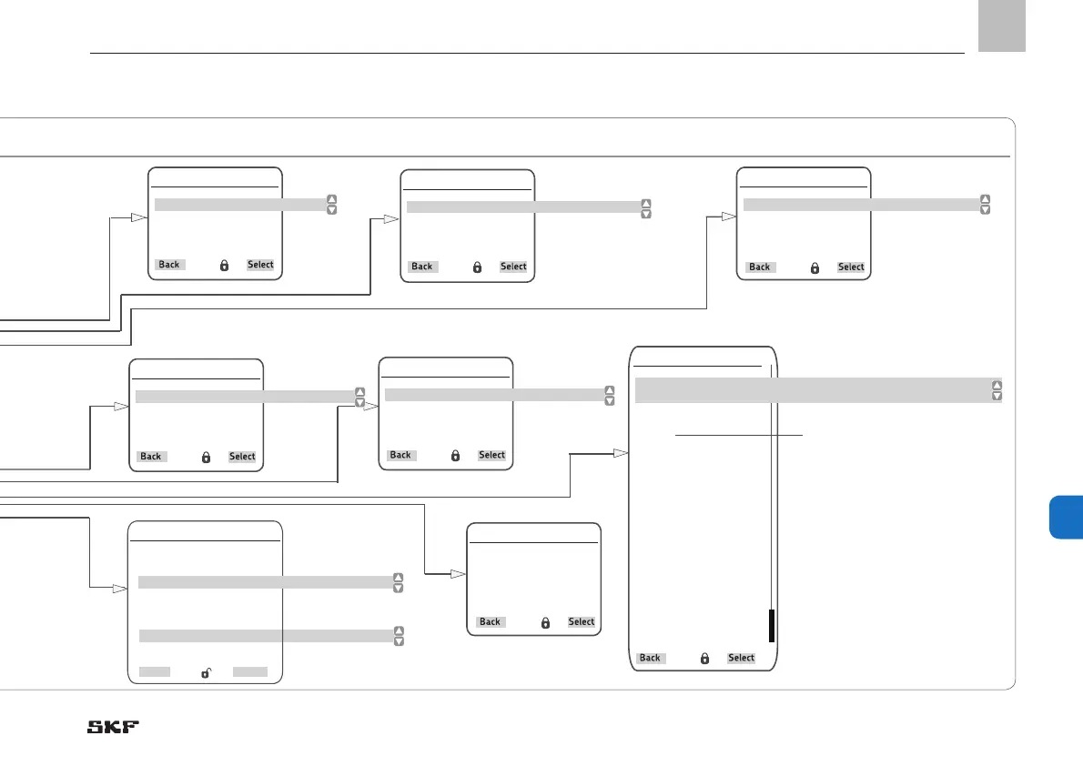
11. System configuration
Setting options for zone settings, Fig. 33
Timings
Control Mode
[ << time controlled >> << Counder ctrld >> ]
Normal Cycle Time
[0000: 00: 00]
Heavy Cycle Time
[0000: 00: 00]
Release/Counter
Input Type
[ << normally closed >> << normally open >> << disabled >> ]
Input No.
[ 1,06 ] DI
Lube Loade
Input Type
[ << normally open >> << normally closed >> << disabled >> ]
Input No.
[ 1,07 ] DI
Valve A
Output Type
[ << normally open> <<normally closed >> << disabled>> ]
Output No.
[ 1,03 ] 0
Valve B
Output Type
[ << normally open> <<normally closed >> << disabled>> ]
Output No.
[ 1,04 ] 0
Press. Sensor at EOL
Sensor Type
[ << disabled >> << transducer 1-6V >> << transducer 4-20 mA >> << transducer 0-20mA >>
<< transducer 2-10V >> << transducer 0-10V >> << normally open >> << normally closed >> ]
Input No. A
[ 1,01 ] AI
Input No. B
[ 1,01 ] AI
Minimal Valve
[ 0000 ] PSI
Maximal Valve
[ 0000 ] PSI
Minimal abs. Valve
[ 0000 ] PSI
Miaximal abs. Valve
[ 0000 ] PSI
Minimal dif.. Valve
[ 0000 ] PSI
Maximal dif. Valve
[ 0000 ] PSI
Note!
Additional buttons
in transducer setting
Lube Control Time
Monitoring Time
[00: 00: 00]
Holding time
[ 00: 00 ] s
Proximity Sensor
Back
Select
Amnt of Proximity Sensor
[ 01]
Input No. 1 Type
[ <<normally closed >><<normally open>> <<pulses>><<disabled>>]
Input No. 1
[ 1,08 ] DI
Input No. 2 Type
[ <<normally closed >><<normally open>> <<pulses>><<disabled>>]
Input No. 2
[ 1,08 ] DI
 Loading...


