• Some practical examples of moving paths include resizing boxes and envelopes where you need the overall
dimensions of the final project to be different but you do not want to change the size/thickness of the flaps.
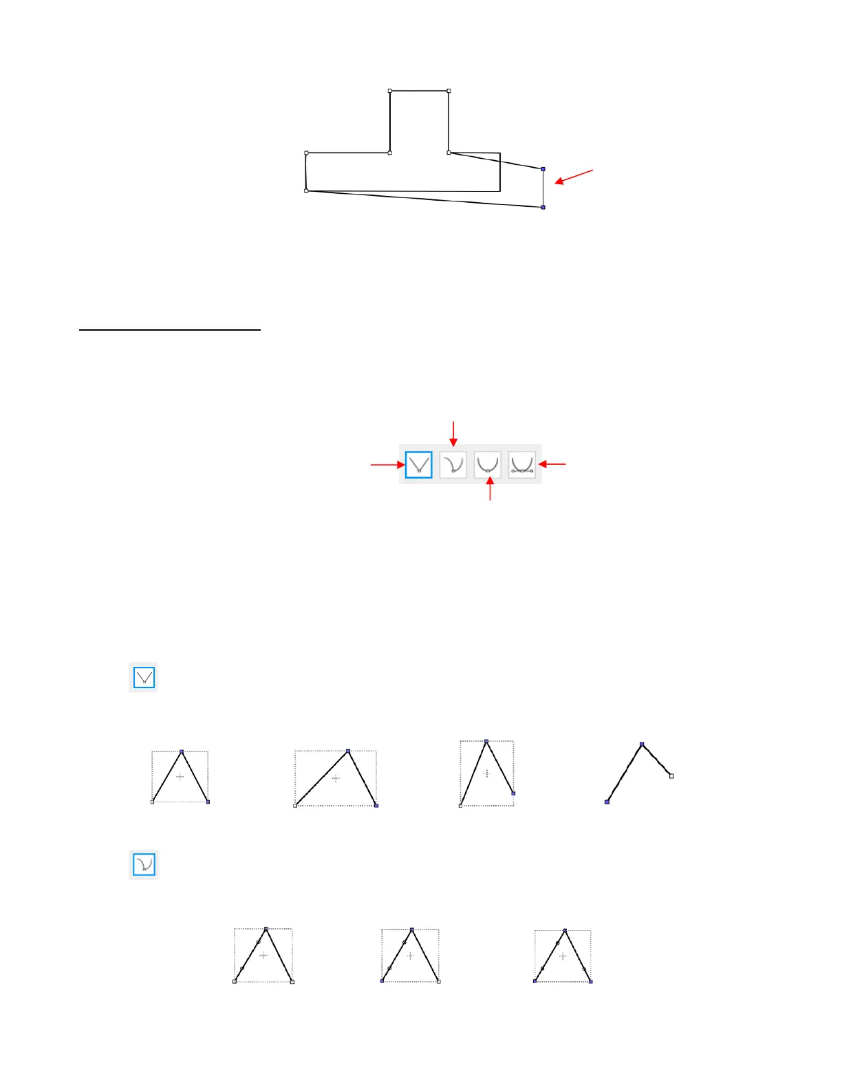
10.10.2 Reshaping a Path
• With the Shape Tool selected, you’ll observe four icons in the Tool Options. The purpose of each option is
to convert one or more selected nodes to that type of node:
• One or more nodes are highlighted and then the appropriate icon selected. These same four functions can
also be accessed by right-clicking and selecting Path>Convert Node to.
• To illustrate each one of these options, a simple path with a sharp corner will be used. This shape is already
in Corner Node mode. To change to a different mode (in the examples that follow the first one), the top
node is selected and then the option is clicked from the Tool Options or using the right-click and
Path>Convert Node to menu option.
Corner Nodes: These are the nodes that make up straight-line shapes such as rectangles,
squares, triangles, stars, etc. Once selected, the shape will appear as below and either path can be
moved as was demonstrated in the prior Section 10.10.1.
Cusp Nodes: In this mode the Bézier control points appear and can be moved independently.
First note how the paths appear when in this mode, depending on how many of the adjacent nodes are
selected:
o The dots along the path are Bézier control points which are not linked to one another. You can
freely drag either or both to create curves: