Can you hear audio on left and right monitors? If you can still only hear audio on the left main and mini monitors then the problem
must be post the source selection and as you can see from the diagram must be a problem on the 629515 assembly.
For the sake of this example we will assume that when you switched to an alternative source you could hear audio on both left
and right monitors indicating that the problem is prior to the monitor source selection. Using the same principle we will try to
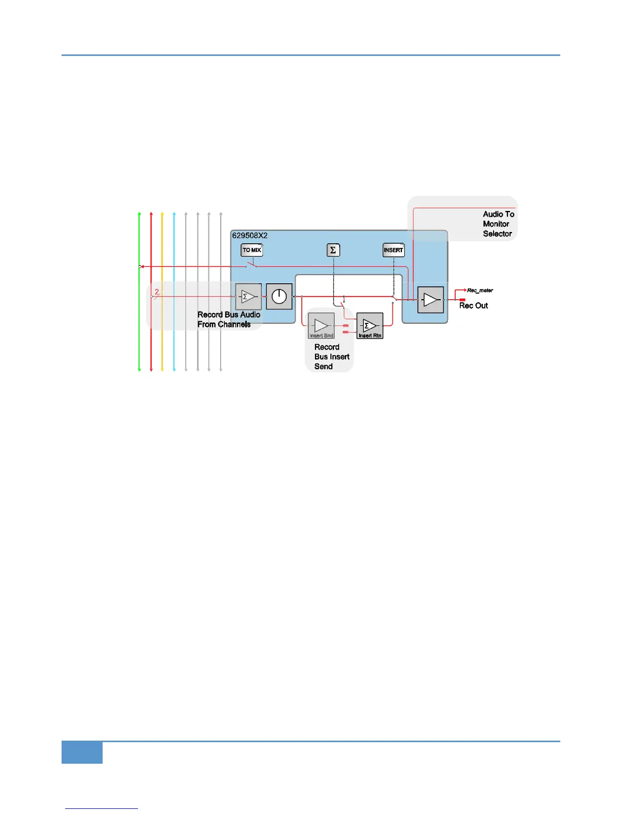
isolate the signal path further. Again referring to the Matrix block schematic sheet 2 you can see that the REC bus feed to the
monitoring is taken from the 629508 assembly which is shaded blue on the left hand side of the diagram. Audio from the channels
o
n the REC bus are summed together by this module. The summed audio is then routed to several destinations including the REC
bus insert send.
Choosing a piece of external equipment which has an input meter, switch the REC bus insert into the signal path. Check the input
meter on the inserted equipment. Can you see signal on both inputs or just the left input? If you can only see signal on the left
channel then it is most likely that the fault lies with the 629508 REC bus assembly.
Again, for the sake of this example, we will assume you can see signal on both inputs. Select the REC bus as the monitor source.
If you can now hear audio on both monitors then the fault is most likely with the switching of the insert return on the 629515
assembly. If you still can only hear audio on the left monitor then the problem is most likely with the 629508.
As you can see in a matter of minutes we have broken down the signal path and identified the faulty module. The next step would
be to follow the module removal instructions later in this section and re-seat the suspected module in its slot to ensure that a
valid connection is made. Once re-seated, test the signal path again. If there is no change, a replacement will be required.
Appendix G - Service
132
Matrix
2
Owner’s Manual