Structure and Functions
5.8 Support stand
The uncoupled machine rests on the support stand. Depending on the
machine’s equipment, it is fitted with:
• a mechanical support stand (standard equipment),
• a hydraulic support stand (optional equipment).
5.8.1 Mechanical support stand
Standard equipment:
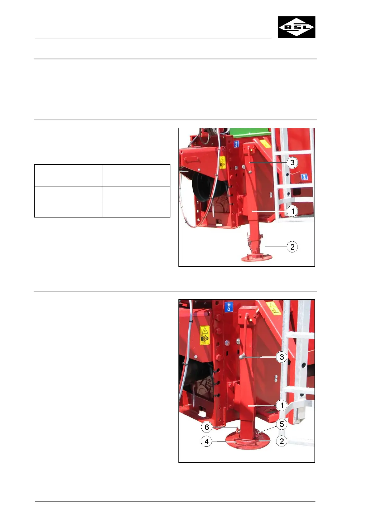
The mechanical support stand (Fig. 53/1) with
spindle adjustment and telescopic quick
adjustment (2) is rotated via the crank handle (3).
Winding direction of
the hand crank
Support stand
clockwise raise (transport position)
anti-clockwise lower (support position)
Fig. 53
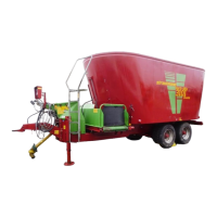
5.8.1.1 Lifting of mechanical support stand to transport position
1. Relieve the support stand via the crank
handle (3).
2. Grip the handle (4) of the telescopic quick
adjustment (2).
3. Release and remove locking pins (5).
5. Secure the support stand in the lifted
transport position by means of the locking
bolt.
6. Secure the locking bolt against accidental
losing by means of the spring cotter (6).
Fig. 54
4. Raise the support stand.
100
Verti Mix Double K Edition 08.08