Structure and Functions
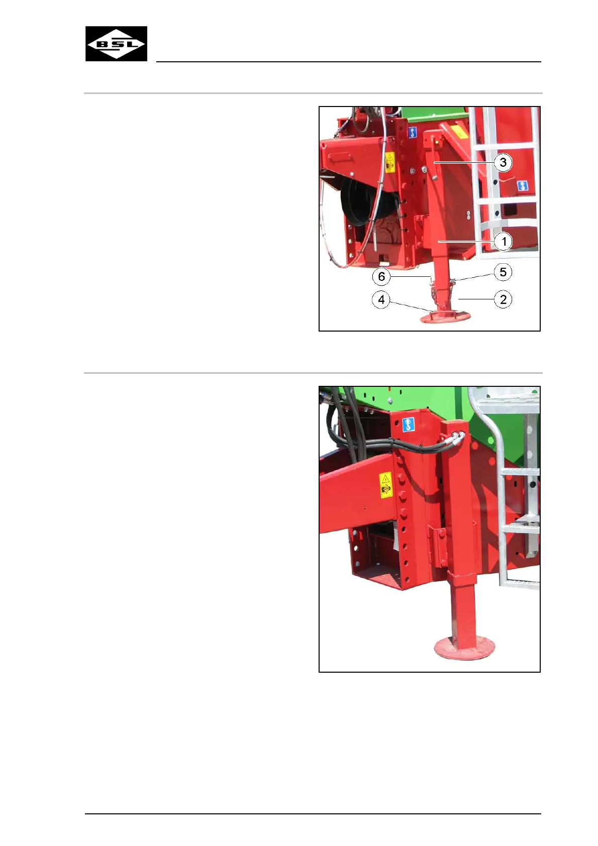
5.8.1.2 Lower mechanical support stand to support position
1. Grip the handle (4) of the telescopic quick
adjustment (2).
2. Release and remove locking pins (5).
4. Secure the support stand in the lowered
support position by means of the locking
bolt.
5. Secure the locking bolt against accidental
losing by means of the spring cotter (6).
6. Use the crank handle (3) to further lower
the support stand.
3. Lower the support stand.
Fig. 55
5.8.2 Hydraulic support stand
Optional equipment:
Depending on the machine’s equipment, the
support stand (Fig. 56) is operated via remote
control from the tractor:
• directly via a double-acting control device of
the tractor (standard equipment),
• via a hand lever (optional equipment),
• via the Bowden cable (optional equipment),
• via electro-hydraulic control (control unit)
(optional equipment).
Fig. 56
Verti Mix Double K Edition
101
08.08
 Loading...