Chapter 4 Mounting the Server Into a 2-Post Rack 63
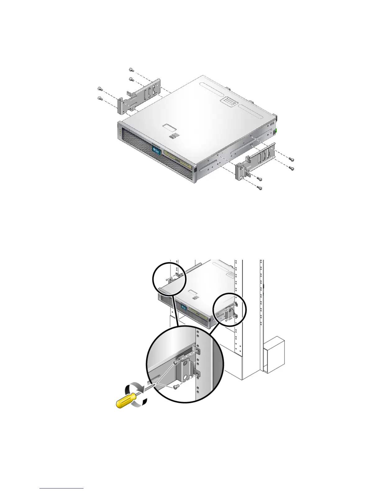
FIGURE 4-9 Securing the Side Brackets to the Side of the Server
3. Lift the server into the rack.
4. Using two screws for each bracket, secure the front of the server to the front of the
rack (
FIGURE 4-10).
FIGURE 4-10 Installing and Securing the Server in the 2-Post Rack