12
44
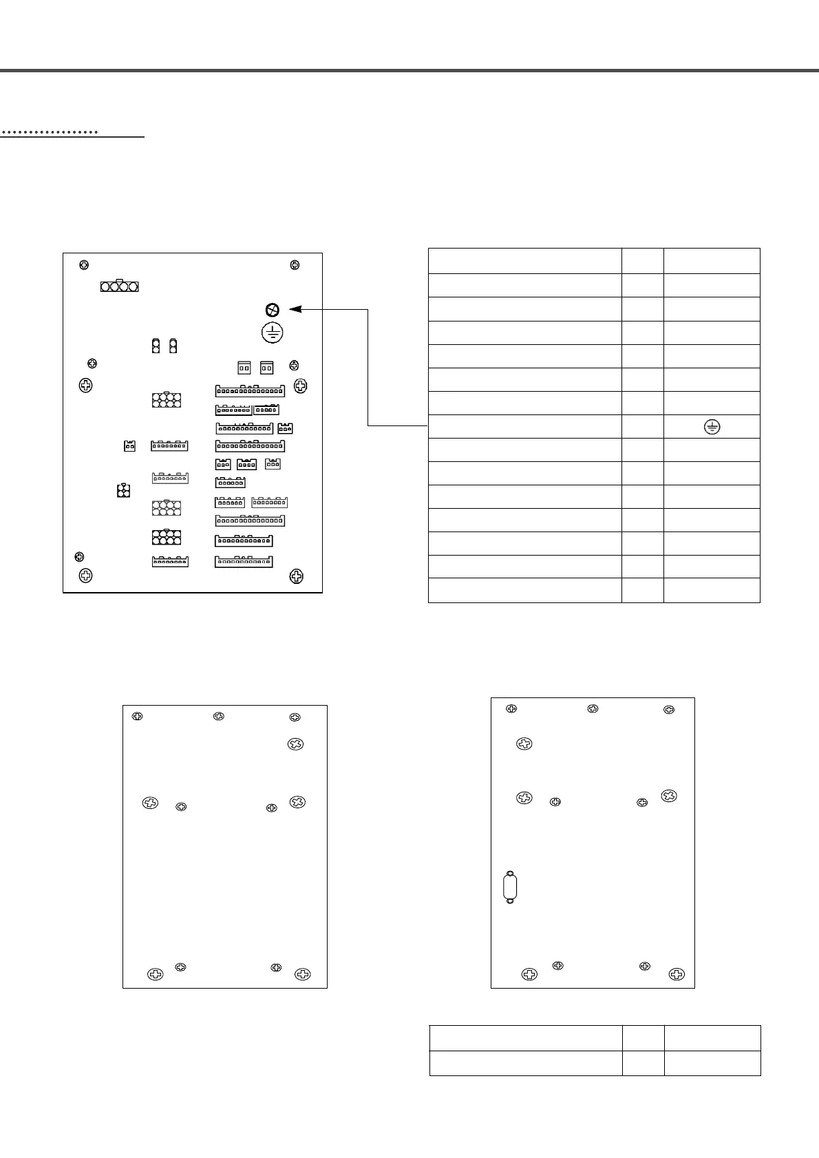
Cable Connection to Control Box
4-1) Internal wiring of the control box
※ Wiring Diagram of Control Box
[Rear Cover of Control Box]빣
[Left Side Cover of Control Box] [Right Side Cover of Control Box]
X(Yellow),Y(Blue),P(Red)-shaft and step motor connection
X(Yellow),Y(Blue),P(Red)-shaft and encoder mid-connection
Thread tension solenoid
AIR solenoid output 1 (White)
OP connection
Hand switch connection
Cables for BH6100 grounding
Pneumatic pressure sensor
PHOTO sensor 2 (Blade Position)
Emergency stop and head safety switch
PHOTO sensor 1 (Phase Stop)
AIR solenoid output 2 (Red)
Starting Point Sensor in the X,Y,P axis (Red)
Thread Detection Sensor
CN11, CN15, CN17
CN22, CN31, CN42
CN7
CN13
CN40
CN44
CN36
CN27
CN34
CN26
CN16
CN43
CN6
Cable Name
Machine
Control Box
Main Shaft Encoder (Sanyo) Input Cable
CN8
Cable Name
Machine
Control Box
4-2) External wiring of the control box
CN8
N46 CN45
CN9 CN7
CN13
CN44
CN11
CN32
CN6
CN22
CN31
CN15
CN17
CN42
CN43
CN38
CN16
CN40
CN33
CN39
CN14
CN36 CN29 CN27
CN34
CN26 CN25