EXCITE + - Crossover: Technical Service guide- Ver. 4.1
Pagina 7.33
7.9.2. DISASSEMBLING THE UPPER BALANCER
Figure 7.9-3
Carry out the procedure described in paragraph:
7.8.2. “Disassembling the lateral guards” and at
the paragraph: 7.9.1. “
lever”.
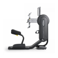
1. Pass the connector (a)
the frame and pull it out from the insi
shown in the figure at the side.
Figure 7.9-4
2. Disconnect the 2 connecting-rod from the
balancer as indicated at paragraph: 7.12.1.
“Disassembling the short connecting-
– L)” and at paragraph: 7.12.2.
“Disassembling the long connecting-rod (R –
L)” at step (3).
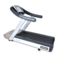
3. Back off the
ring nut inside the lever balancer
(b)
using a 14mm hexagonal wrench,
counter-clockwise
as indicated by the arrow
(apply an extension to the wrench to exert
more force).
CAUTION: During the reassembly
blocking the lever using a torque
wrench set for 200Nm.
Figure 7.9-5
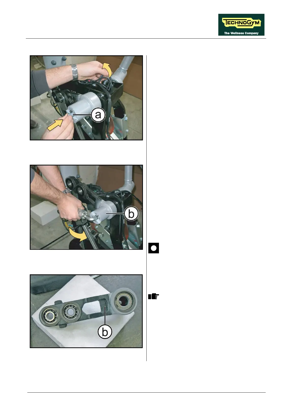
The bearings are press assembled and
locked with an internal snap ring. DO
NOT remove them but if necessary,
replace the complete balancer.
To reassemble the balancer,
follows the above steps in the reverse order.