SYNCHRO Excite +: Service & maintenance manual - rev. 7.1
Page 6.7
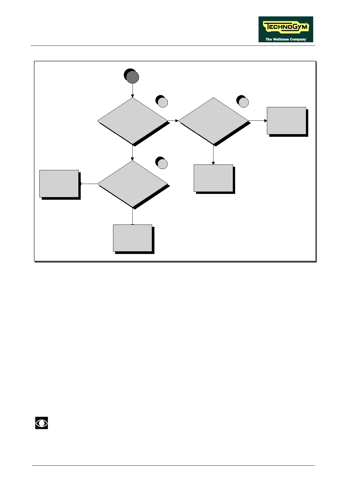
2
Chack the cable that
connect the Low Kit
with High Kit.
YES
NO
Is the voltage at the input
of the Brake Board
correct?
NO
YES
Replace
CU309 cable
NO
Replace the power
entry module
YES
Are the voltages at the
output of the Barke Board
correct?
NO
Replace the
Brake Board
4
A
3
Is the voltage at the
output of the power entry
module correct?
Follow the procedure step by step to correctly diagnose the problem. Take particular care with the
checks highlighted by circled numbers, which are described in detail below:
(1) Check the LEDs 1 and 2 (green and yellow), of Display Board, are correctly lit on.
(2) Place the tester probes across pins 3 and 1 of CN4 connectors on the Brake Board. The
measured value should be approximately 220Vac or 110Vac depending on the mains voltage.
(3) Slightly lift up the Faston on the machine power entry module. Place the tester probes across
the live and neutral pins on the same connector. The measured value should be approximately
220Vac or 110Vac depending on the mains voltage.
(4) Using a tester, check that all the output voltages on connector CN1 of the Brake board. The
measured value should be:
• +12Vdc between pins 6-2;
• +5Vdc between pins 7-3.
If you replace Display Board and/or Brake Board, check that its SW version is
updated, otherwise install the latest version.