Oscilloscope R eference Select the termination
To use
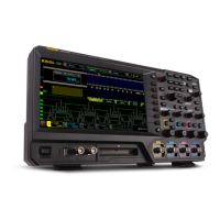
Use the Te rmination controls to select the channel input resistance:
For <4 GHz oscilloscopes:
Select 1 MΩ for use with high impedance passive probes (see page 491).
Select 50 Ω for use with most active p robes (see page 491) and low impedance (Zo) probes (see
page 958).
NOTE. Termination is automatically set for TPP0500 and TPP1000 Series probes on the MSO/DPO5000
Series instruments.
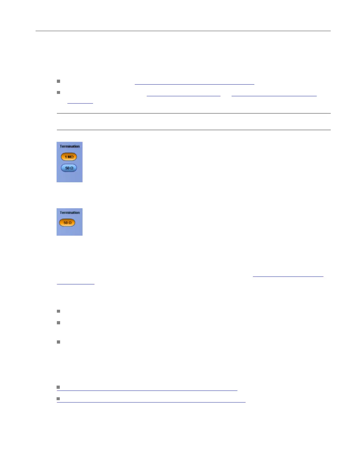
For ≥4 G Hz oscilloscopes, Termination is fixed at 50 Ω.
Behavior
The correct termination is set automatically when you attach a probe with a TekProbe/TekVPI interface
(see page 491) to the instrument. However, you may have to set the termination manually if you use
a probe without a TekProbe Interface.
Consider the following when using 50 Ω termination with any channel:
AC coupling is not available with 50 Ω termination.
The instrument reduces the maximum vertical scale setting for the channel with a X10 probe attached,
since the amplitudes appropriate for the higher settings would overload the 50 Ω input.
The instrument switches to 50 Ω and disables AC coupling (and switches coupling to DC if AC is
selected) if you connect a n active probe. The active probes also reduce the maximum vertical scale
setting as described above. This behavior results in 50 Ω, nonalternating current coupling, which is
appropriate for active probes.
What do you want to do next?
Continue to learn about the Vertical Setup controls. (see page 951)
Return to the Vertical Setup control window overview. (see page 481)
DSA/DPO70000D, MSO/DPO/DSA70000C, DPO7000C, and MSO/DPO5000 Series 957
 Loading...