G10 Installation Guide 7.13.2 134
C
Rev. 005-140228
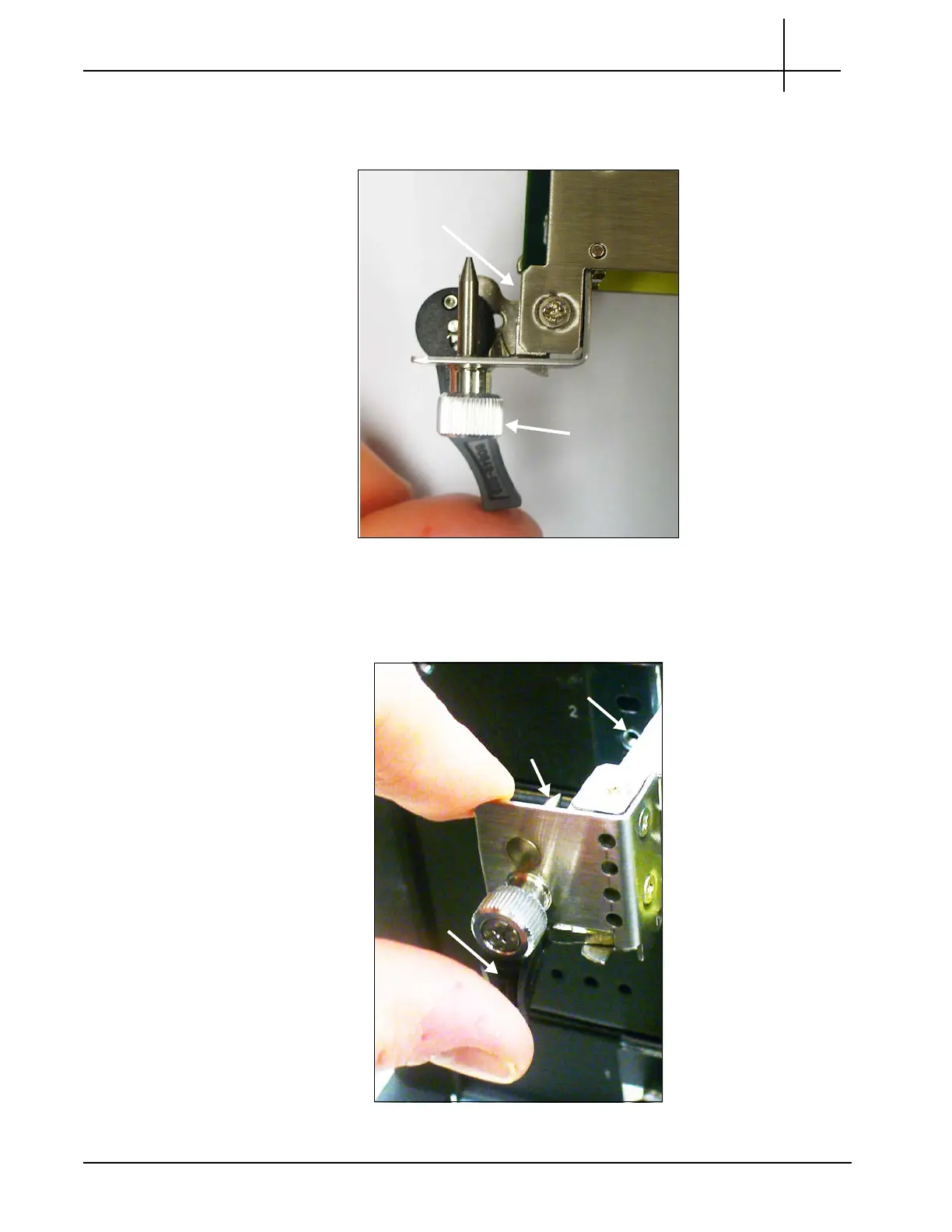
4. Swing the ejector handles inward until they snap into place just beneath the
blade screws (Figure C.29). Be sure to release the ejector handles before
swinging them inward so the blade latches remain in the open position.
Figure C.29 - G10 IIC Ejector Handle - Open Blade Latch
5. Position your thumbs and forefingers as shown in Figure C.30 and slide the
blade into the chassis until the positioning
pins are inserted in the positioning
holes in the shelf.
Figure C.30 - G10 IIC Positioning Pin Alignment
Blade Latch
Open Fully
Blade Screw
Ejector
Handle
Positioning Hole
Positioning
Pin
Tektronix Communications | For Licensed Users | Unauthorized Duplication and Distribution Prohibited
 Loading...
