System Manual 6. Maintenance
76.7300FP11/2, Rev A 8/09 Page 2-97
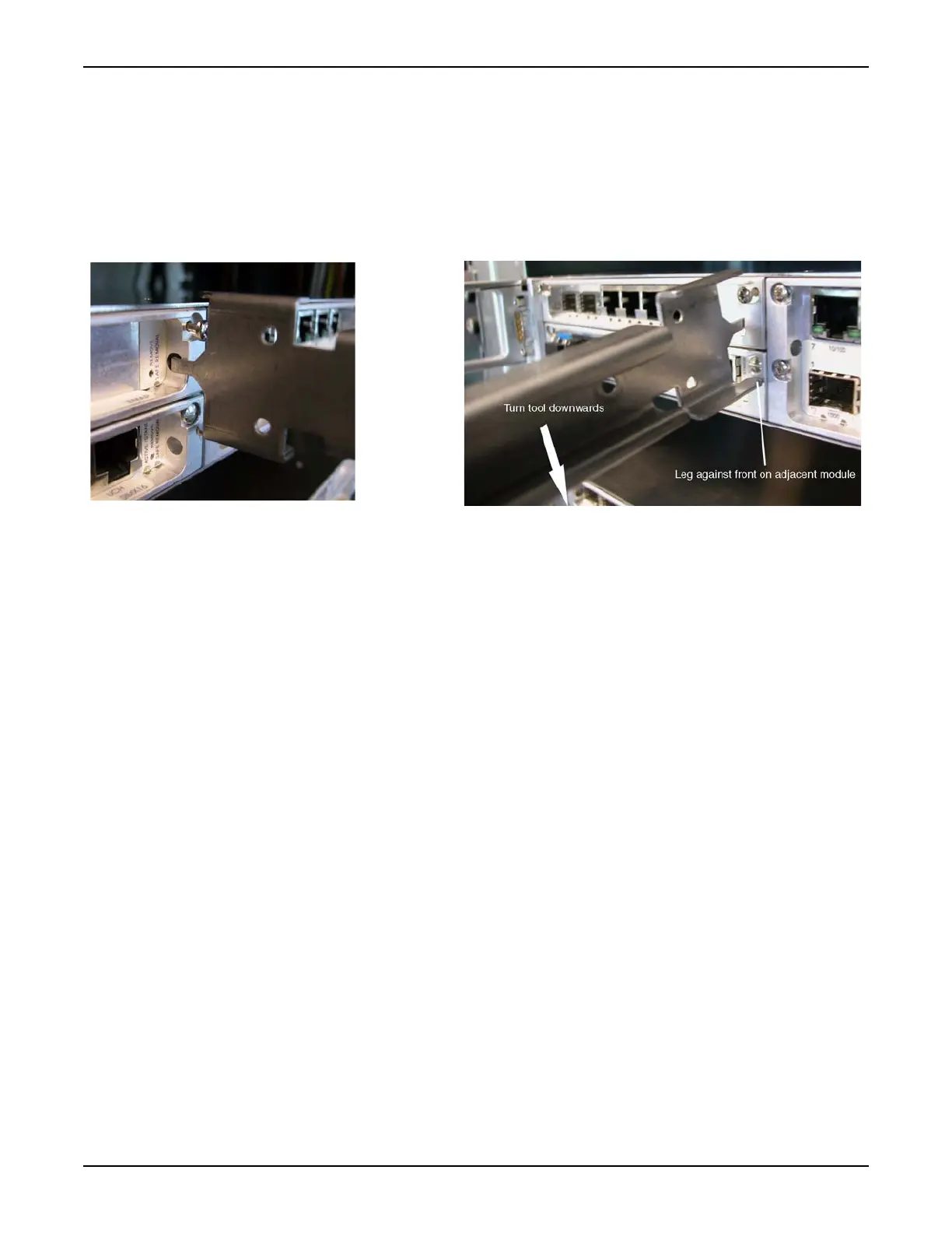
__ 6. Place the pin of the ejector tool (Tellabs part number
81.73EXT-TOOL) in the hole on the module and turn the ejector tool
down or up (depending whether the module to be extracted is placed
in an upper or lower slot of the shelf) pressing one of the legs of the
tool against the front of an adjacent module in the shelf. Push the
ejector tool downward to eject the module. Refer to Figure 6.7,
page 2-97.
Figure 6.7 Using the Module Extraction/Reset Tool
__ 7. Pull out the module and store it in its antistatic packaging.
__ 8. Remove the replacement PSU module from its antistatic packaging.
__ 9. Install the replacement PSU module in the shelf.
__ 10. Securely fasten the replacement PSU module to the shelf with the
included screws.
__ 11. Reconnect all cables to the replacement PSU module.
__ 12. Connect power by either switching on or reinserting the fuses from the
PDP/PDU. The power supply has been connected correctly when the
green LED on the PSU module lights.

 Loading...