ServicingtheLiftControlManifold
g216667
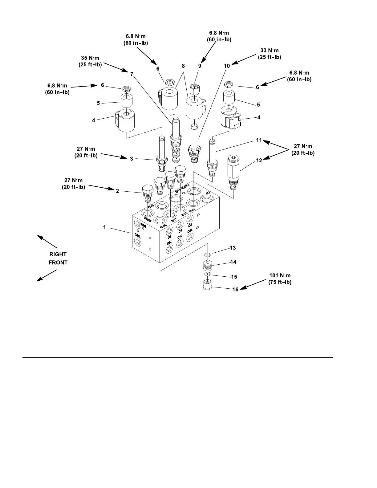
Figure169
1.Liftcontrolmanifold5.Solenoidcoilspacer
9.Nut
13.O-ring
2.Checkvalve(4each)
6.Nut
10.Solenoidreliefvalve
(SVRV)
14.Pilotpiston(4each)
3.Solenoidvalve(SV3)7.Solenoidvalve(SV2)11.Solenoidvalve(SV1)15.O-ring
4.Solenoidcoil8.Solenoidcoil12.Reliefvalve(R7)16.Hexplug(4each)
Note:Theportsontheliftcontrolmanifoldaremarkedforeasyidentication
ofthecomponents.Example:Pisthegearpump(P4)connectionportand
SV2isthelocationforsolenoidvalveSV2;refertotheHydraulicSchematicin
AppendixA(pageA–1)toidentifythefunctionofthehydrauliclinesandcartridge
valvesateachmanifoldport.
Forthecontrolmanifoldserviceprocedures;refertoServicingaControlManifold
CartridgeValve(page6–200).RefertoFigure169forcartridgevalveinstallation
torque.RefertoFigure170forhydraulicttinginstallationtorquevalues.
Note:SolenoidvalvesSV1andSV2ontheliftcontrolmanifolduseacoilspacer
betweenthesolenoidcoilandnut.
HydraulicSystem:ServiceandRepairs
Page6–198
Reelmaster
®
5410/5510/5610Series
15216SLRevC
 Loading...

