ReelAssembly(cuttingunitswithpaintedsideplates)
g214498
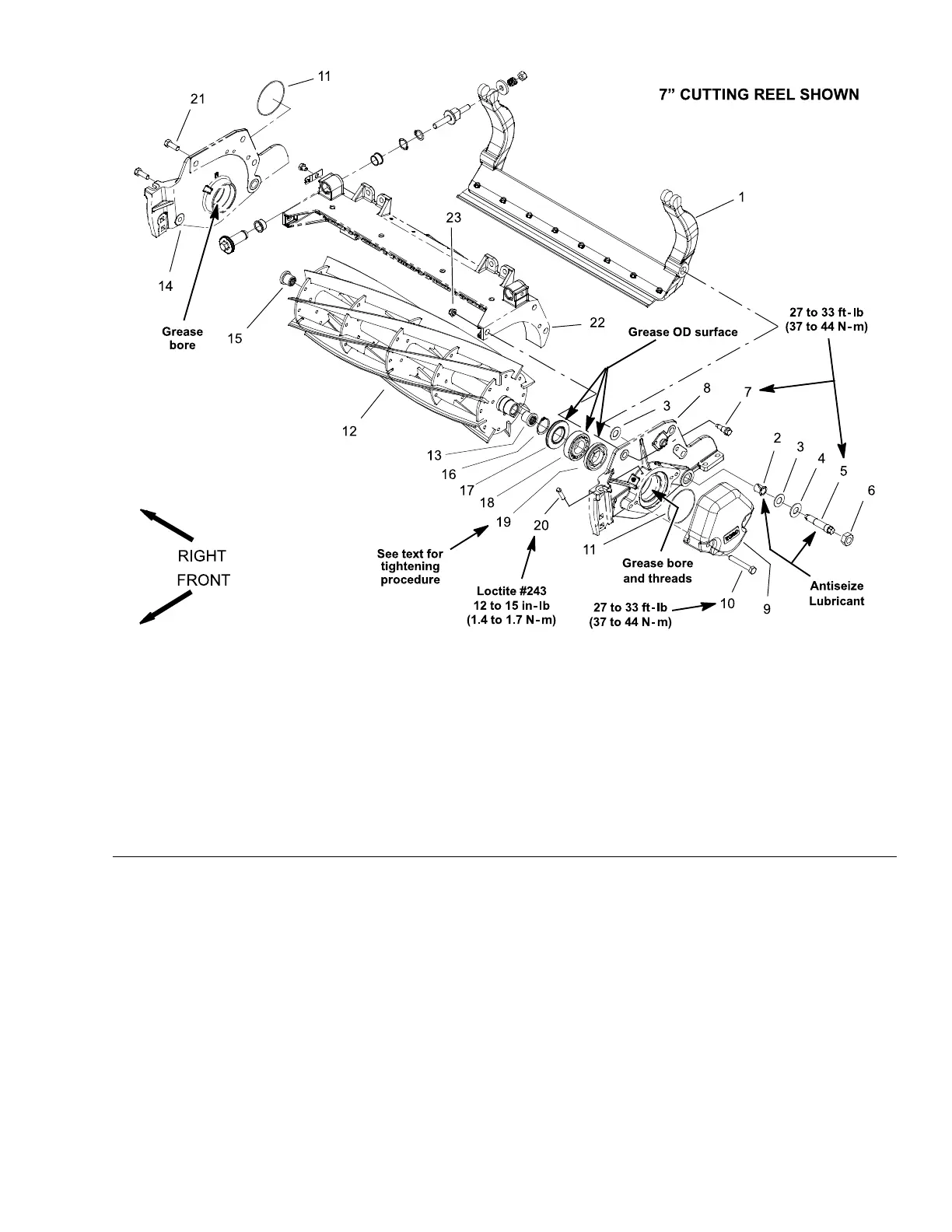
Figure339
1.Bedbarassembly9.Weight
17.Greaseseal(2each)
2.Flangebushing(2each)10.Capscrew(2each)18.Bearing(2each)
3.Plasticwasher(4each)11.O-ring
19.Bearingadjusternut
4.Metalwasher(2each)12.Cuttingreel
20.Setscrew
5.Bedbarpivotbolt(2each)13.Splineinsert(left-handthread)21.Capscrew(2each)
6.Locknut(2each)
14.RHsideplate
22.Cuttingunitframe
7.Shoulderbolt(3persideplate)15.Splineinsert(right-handthread)23.Flangenut(3persideplate)
8.LHsideplate
16.Retainingring(2each)
Note:Thissectionprovidestheprocedureforremovingandinstallingthecutting
reelassembly(cuttingreel,splineinserts,greasesealsandbearings)fromthe
cuttingunit.
Note:RefertoReelAssemblyService(cuttingunitswithpaintedsideplates)
(page9–33)forinformationonreplacingcuttingreelgreaseseals,bearings
andsplineinserts.
Note:RemovalofthecuttingreelrequiresremovaloftheLHsideplatefrom
thecuttingunitframe.TheRHsideplatedoesnothavetoberemovedfrom
theframe.
RemovingtheReelAssembly
1.Parkthemachineonacleanandlevelsurface,lowerthecuttingunits,shut
offtheengine,settheparkingbrake,andremovethekeyfromthekeyswitch.
Reelmaster
®
5410/5510/5610Series
Page9–29
CuttingUnit:ServiceandRepairs
15216SLRevC
 Loading...

