BacklapSwitches
g214065
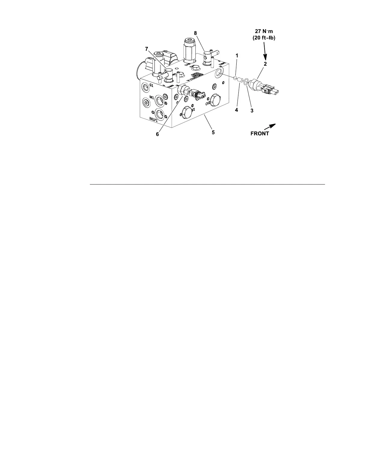
Figure253
1.Ball4.Dowelpin7.Rearbacklaplever
2.Frontbacklapswitch
5.Mowcontrolmanifold
8.Frontbacklaplever
3.O-ring
6.Rearbacklapswitch
Thefrontandrearbacklapswitchesarenormallyclosedballswitchesthatare
inthenormal,closedstatewhenabacklapleveronthehydraulicmowcontrol
manifoldisintheBACKLAPposition.WhenabacklapleverisintheMOWposition,
theswitchopens.Thebacklapswitchesareattachedtothehydraulicmow
controlmanifoldlocatedundertheseat(Figure253).
TheToroElectronicController(TEC)usesthebacklapswitchesasinputsto
preventsomenormaloperationsduringbacklapping(e.g.,topreventthecutting
reelsfromraisingduringbacklapping).
TestingtheBacklapSwitches
1.Parkthemachineonalevelsurface,lowerthecuttingunits,settheparking
brake,andshutofftheengine.
2.Beforeyoudisconnectthebacklapswitchfortesting,ensurethatyoutestthe
switchanditscircuitwiringasTECinputwiththeInfoCenterdisplay;referto
UsingtheInfoCenterDisplayforTroubleshooting(page7–28).
3.IftheInfoCenterveriesthatthebacklapswitchandcircuitwiringare
functioningcorrectly,nofurtherswitchtestingisnecessary.
4.IftheInfoCenterdeterminesthatthebacklapswitchandcircuitwiringarenot
functioningcorrectly,proceedwiththetest.
5.EnsurethatthekeyswitchisintheOFFposition.
6.Raiseandsecuretheoperatorseattogetaccesstothebacklapswitch.
Locatethebacklapswitchonthehydraulicmowcontrolmanifold(Figure253).
7.Disconnectthewireharnesselectricalconnectorfromthebacklapswitch.
8.Checkthecontinuityoftheswitchbyconnectingamultimeter(ohmssetting)
acrosstheswitchconnectorterminals.
9.WiththekeyswitchintheOFFposition,turnthebacklaplevertothebacklap
positionwhilewatchingthemultimeter.Continuityshouldbemadeasthe
switchcloses.
10.TurnthebacklaplevertotheMOWpositionwhilewatchingthemultimeter.
Continuityshouldbebrokenastheswitchopens.
ElectricalSystem:TestingtheElectricalComponents
Page7–84
Reelmaster
®
5410/5510/5610Series
15216SLRevC
 Loading...

