Implementation of Modbus TCP
D301271 1013 - FGEN - multi protocol9-10
9.3.1 Data width of the I/O-modules in the modbus-register area
The following table shows the data width of the FGEN-stations within the modbus register area and the
type of data alignment.
diagnostics (max. 2 registers per station) 0×A000,
00A001
40960,
40961
- 440961,
440962
diagnostics (max. 4 registers per station) 0×B000,
0×B001
45056,
45057
- 445057,
445058
Table 9-5:
(process data
length of the
stations
Station Process input Process output Alignment
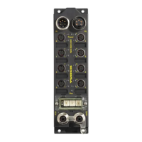
FGEN-IM16-x001 16 Bit - bit by bit
FGEN-OM16-x001 - 16 Bit bit by bit
FGEN-IOM88-x001 8 Bit 8 Bit bit by bit
FGEN-XSG16-x001 16 Bit 16 Bit bit by bit
Table 9-4:
Mapping of
Modbus regis-
ters (holding
registers)
Description Hex Decimal 5-digit Modicon

 Loading...