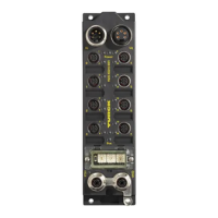
D301271 1013 - FGEN - multi protocol
6-3
FGEN-IOM88-x001
6.1.2 Wiring diagrams
Ethernet
→ Ethernet (page 3-6)
Power supply
→ Operating/load voltage (page 3-6)
6.1.3 Parameters
Further information about the parameter data mapping can be found in the fieldbus specific chapters.
EtherNet/IP™: chapter 7.4.4, Digital Versatile Module Class (VSC117) (page 7-34) ff.
Modbus TCP: chapter 9.3.2, Register mapping of the FGEN-stations (page 9-11) ff.
PROFINET: chapter 11.4, Parameters (page 11-5)
Figure 6-1:
Wiring diagram
input M12 x 1
Figure 6-2:
Wiring diagram
output M12 x 1
Table 6-2:
Parameters
Parameter name Value Description
A default
setting
Digital input
(Inv. DIx)
0 = normal A
1 = inverted Inverts the digital input signal.
Output on
overcurrent
(SROx)
0 = activated
A The output switches on automatically after an overload.
1 = deactivated The output is manually switched-off after an overload.until
a new set-command is given (rise and fall).
5 PE
4 BK
1 BN +
3 BU
3 BU
2 WH
v
C0...C3
5 PE
4 BK +
1
2 WH +
3 BU
v
C4...C7

 Loading...