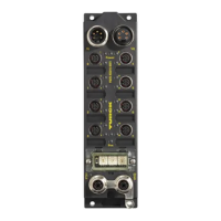
FGEN – general technical properties
D301271 1013 - FGEN - multi protocol3-6
3.4 Connection possibilities
3.4.1 Ethernet
The connection to Ethernet via the integrated auto-crossing switch is done using two 4-pole, D-coded
M12 x 1-Ethernet-female connectors.
Ethernet-connection in QC-/FSU-applications
3.4.2 Operating/load voltage
The power supply is realized via 7/8" connectors on the module.
These connectors are designed either 4- or 5-pole.
Figure 3-2:
Pin assignment
of the M12 x 1-
female connec-
tors, 4-pole
Female connectors M12 x 1
ETH1 ETH2
Note
Please observe the following for QuickConnect (QC)- and Fast Start-Up (FSU)-applications:
– do not use a crossover-cable
– ETH1 = connector for incoming Ethernet-line
– ETH2 = connector for outgoing Ethernet-line
Figure 3-3:
Power supply
U
I
= voltage IN
U
O
= voltage OUT for supplying the next node
Note
The operation voltage (U
B
) and the load voltage (U
L
) are fed and monitored separately. If the
voltage falls below the permissible voltage, the outputs are switched off.
U
L
can be switched off. In this case, the module still communicates and the inputs are still read
in.
In case of an undervoltage at U
L
, the "POWER" LED changes from green to red. In case of an
undervoltage at U
B
, the "POWER" LED is turned off.
v
4
1
3
2
v
C10 C11
4
1
3
2
1 = TD + (YE)
2 = RD + (WH)
3 = TD (OG)
4 = RD (BU)

 Loading...