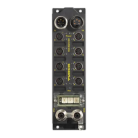
D301271 1013 - FGEN - multi protocol
3-7
Connection possibilities
Voltage supply via 7/8’’, 5-pole (FGEN-xxxxx-5xx1)
Voltage supply via 7/8’’, 4-pole (FGEN-xxxxx-4xx1)
3.4.3 Analog inputs and outputs
The module is equipped throughout with metal M12 connectors for connection of the sensor/actuator
level.
Figure 3-4:
7/8’’ male and
female,
5-pole
U
L
and U
B
galvanically isolated. No galvanic isolation of U
L
and U
B
at the
FGEN-XSG16-5001
Figure 3-5:
7/8’’ male and
female, 4-pole
U
U
L
and U
B
galvanically isolated. No galvanic isolation of U
L
and U
B
at the
FGEN-XSG16-4001!
Note
For the pin assignment of the M12-connectors, please refer to the wiring diagrams in the
station-specific chapters of this manual.
1 = GND
L
2 = GND
B
3 = PE
4 = U
B
5 = U
L
3
4
5
2
1
wv
3
4
5
2
1
1 = GND
L
2 = GND
B
3 = PE
4 = U
B
5 = U
L
3
4
5
2
1
wv
3
4
5
2
1
1 = GND
2 = GND
3 = FE
4 = U
B
5 = U
L
3
4
5
2
1
3
4
5
2
1
wv
1
2
3
4
1 = Aux +
2 = E +
3 = E
4 = Aux
1
2
3
4
1
2
3
4
1 = U
L
2 = U
B
3 = GND-B
4 = GND-L
1
2
3
4
wv
1
2
3
4
1 = Aux +
2 = E +
3 = E
4=Aux
1
2
3
4
1
2
3
4
1 = U
L
2 = U
B
3 = GND
4 = GND
1
2
3
4

 Loading...