15.RS-485 COMMUNICATION INTERFACE(OPTION)
98
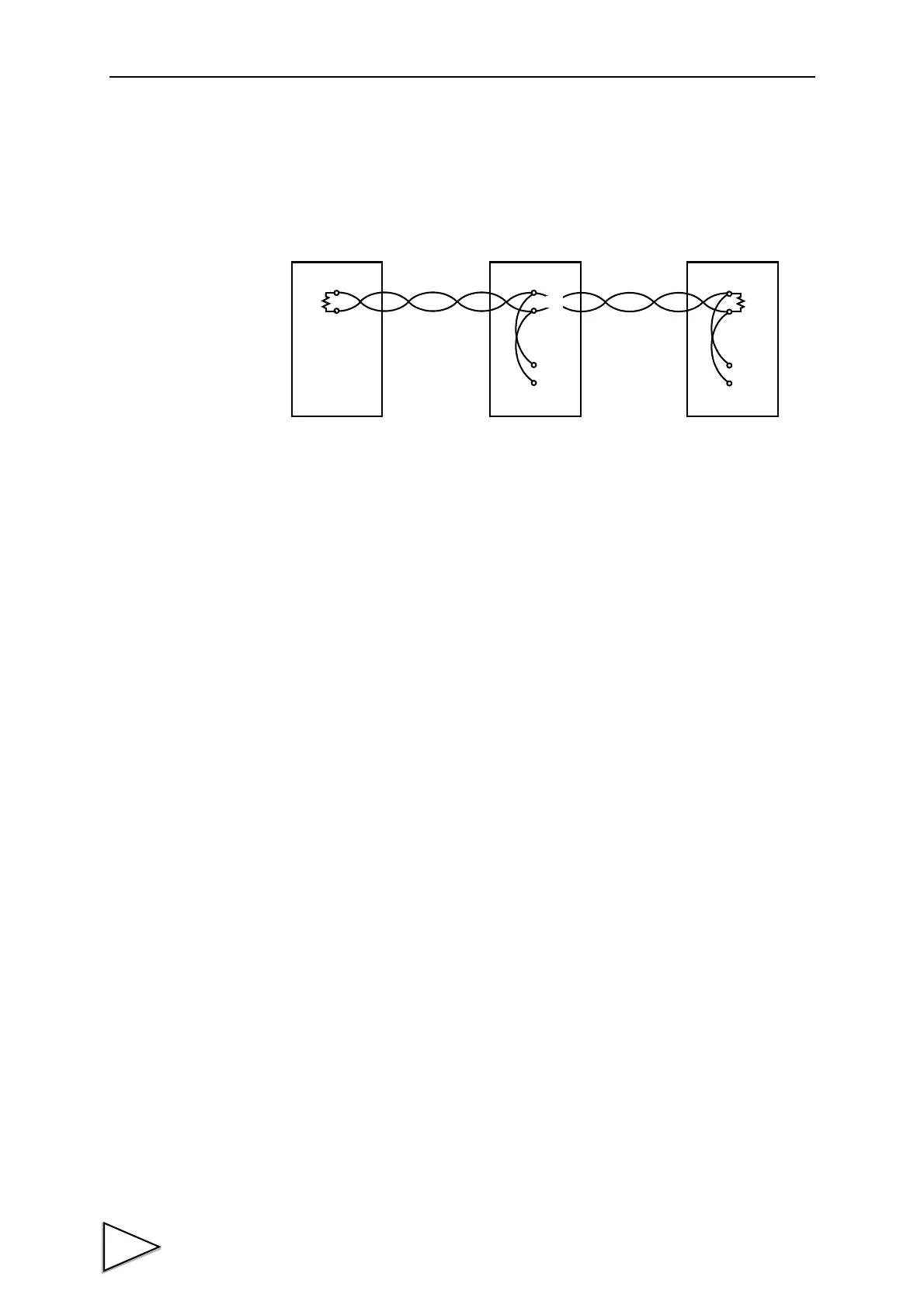
② 2-wire connection
Set the communications mode of the F371 to “2-wire.”
First, connect “A-” of “RD” and “SD”, and “B+” of “RD” and “SD” of the F371.
Next, connect the target equipment with the same polarity. (See "2. Polarity")
2. Polarity
Basically, connect “A” or “-” of the equipment on the other end to “A-” of the F371, and
“B” or “+” of the equipment on the other end to “B+” of the F371.
(In some rare cases, the signal polarity (A/B notation) may be reversed, so that
communications cannot be made even with correct connection. In such cases, connect by
reversing the signal polarity.)
3. Terminal resistor
Mount a terminal resistor of approx. 100 – 200Ω on the receiving side.
(The F371 can also be set to connect 120Ω internally.)
In the case of 2-wire, it should be connected to both ends because the sending and
receiving signal lines are the same. (See the connection diagram.)
4. SG terminal
This is the ground for signal lines. When connecting to the SG terminal of the equipment
on the other end, connect after checking the specifications of the equipment on the other
end.
RD
A
B
F371
(Master)
A
B
RD
A
B
SD
F371
A
B
A
B
SD

 Loading...