2-30 Setting Up the Detector
Lamp on/off connections
To make lamp on/off connections:
1. Make the lamp on/off connections shown in the following table and
figure with a signal cable.
2. Configure the lamp on/off signal at the detector’s front panel by
changing the default from Ignore to High or Low (see page 3-25).
3. Using the signal cable, make the lamp on/off connections from the pump
controller to the detector shown in the following table and figure.
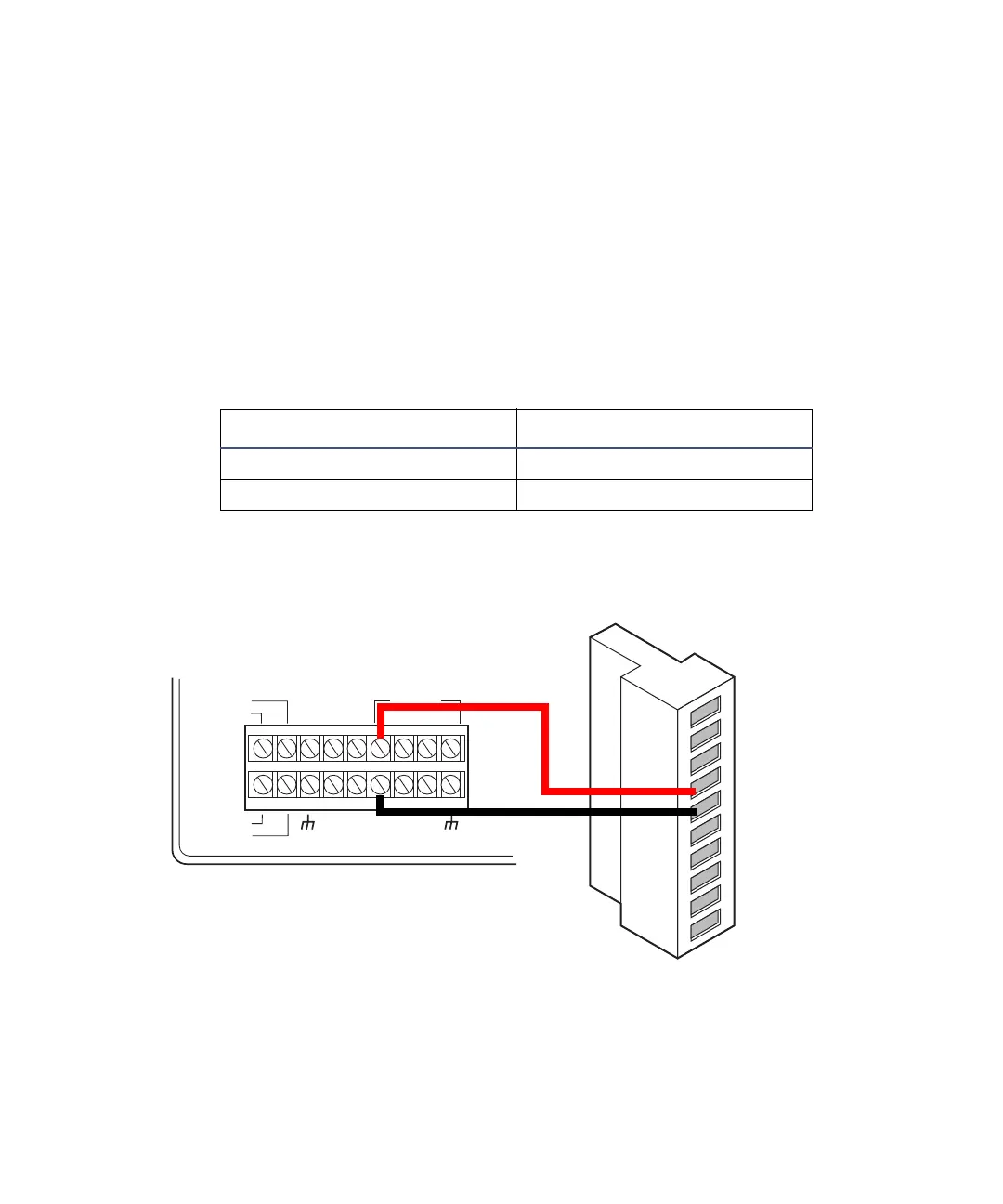
Lamp on/off connections for the 600-series pump
Detector inputs and 600-series pump terminal connections
600-series pump terminal 2475 detector (A inputs)
S1, S2, S3, or S4 Pin 4 Lamp On/Off +
GND (any one of four) Pin 5 Lamp On/Off –
INJECT
STOP
FLOW
HOLD
S1
S2
S3
S4
SWITCHES
CHART+
PRESSURE+
CHART
_
PRESSURE
_
GND
GND
GND
GND
AUX.
+
12V
2475 detector
A (inputs and outputs)
600-series pump
1
2
3
4
5
6
7
8
9
10
+
−
+
−
+
−
+
−
Inject start 1
Inject start 1
Ground
Lamp on/off
Lamp on/off
Chart mark
Chart mark
Ground
Auto zero
Auto zero
Red
Black