2-32 Setting Up the Detector
2. Program the pump to provide a pulse output on the selected switch at
the beginning of each run. See the Waters 600E Multisolvent Delivery
System User’s Guide.
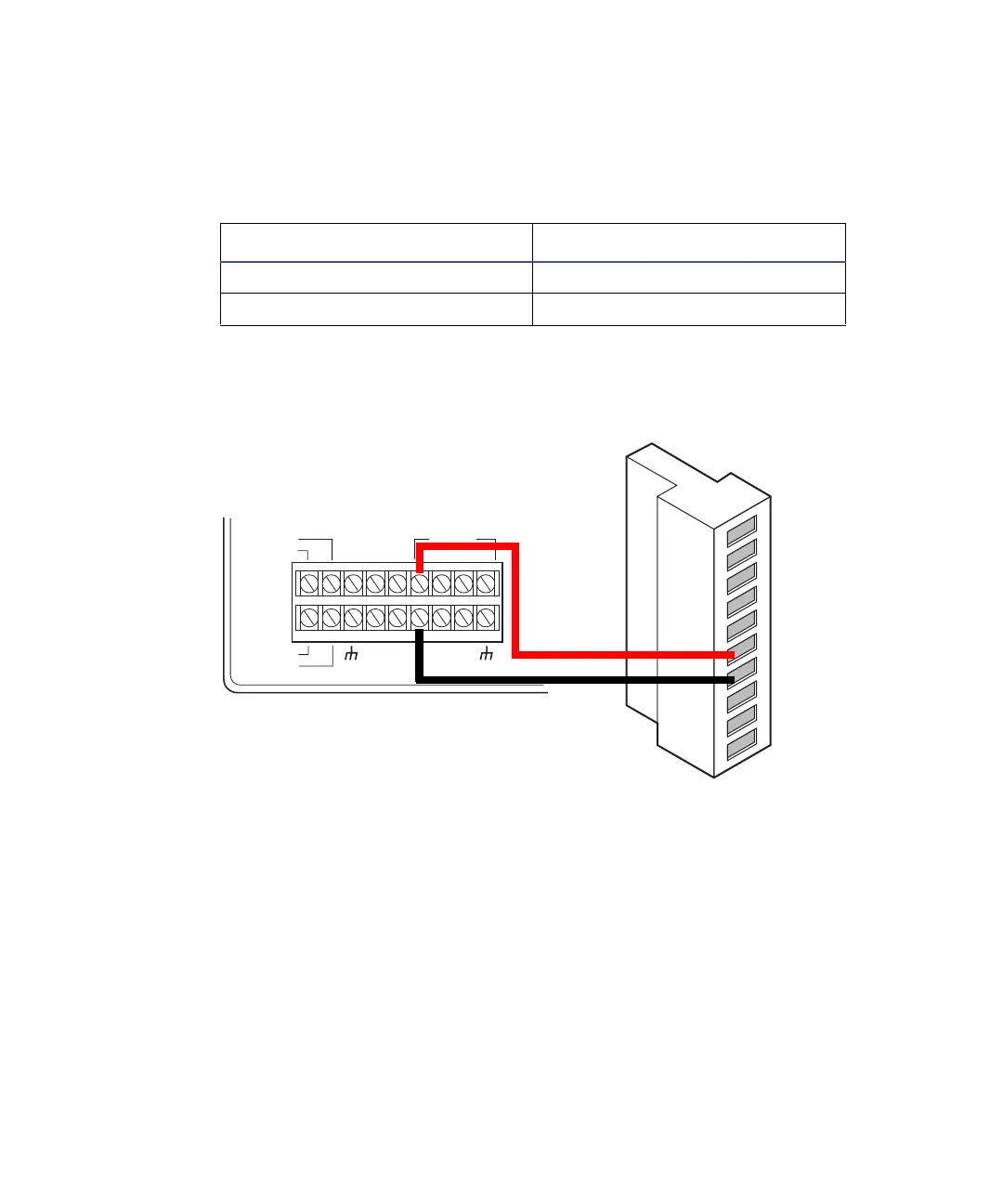
Chart-mark connections for the 600-series pump
Inject-start connections
When the detector is connected to an Empower system or Millennium
32
chromatography workstation, the inject-start connections allow it to initiate
data acquisition.
To make inject-start connections:
1. Make the connections shown in the following table and figure with a
signal cable.
Chart-mark connections for the 600-series pump
600-series pump terminal 2475 detector (A inputs)
S1, S2, S3, or S4 Pin 6 Chart Mark +
GND (any one of four) Pin 7 Chart Mark –
INJECT
STOP
FLOW
HOLD
S1
S2
S3
S4
SWITCHES
CHART+
PRESSURE+
CHART
_
PRESSURE
_
GND
GND
GND
GND
AUX.
+
12V
600-series pump
2475 detector
A (inputs and outputs)
1
2
3
4
5
6
7
8
9
10
+
−
+
−
+
−
+
−
Inject start 1
Inject start 1
Ground
Lamp on/off
Lamp on/off
Chart mark
Chart mark
Ground
Auto zero
Auto zero
Red
Black