Manual 37128A GCP-20 Series - Genset Control
© Woodward Page 121/190
Battery Voltage Monitoring
Parameter 188
Batt.undervolt.
U < 00.0V
Battery voltage monitoring: Threshold value 8 to 35 V
If the measured value falls below this threshold value for at least the delay time
(
Parameter 189), the following alarm class is issued.
Issuing of class F1 alarm
Parameter 189
Batt.undervolt.
Delay 00s
Battery undervoltage delay 0 to 999 s
For the control unit to recognize a battery undervoltage fault condition, the thresh-
old value configured in
Parameter 188 must be exceeded without interruption for
this period of time.
Note: Regardless of the configured battery voltage monitoring threshold, readiness
for operation is withdrawn and an alarm message is issued if the power supply volt-
age falls below 9 Vdc or if the power supply voltage falls below 11 Vdc during the
start sequence.
Discrete Inputs
≡≡≡≡≡≡≡≡≡≡≡≡≡≡≡≡≡≡≡≡≡≡≡≡≡
Parameter 190
Configure
dig.inputs YES
Configuration of discrete inputs YES/NO
Parameters are grouped together in blocks to permit quicker navigation through the
large number of configuration screens. Selecting "YES" or "NO" has no effect if
controlling or monitoring is performed. This parameter has the following effects:
YES.............. The configuration screens in the next block are displayed and can ei-
ther be viewed ("Select" push-button) or modified ("Cursor →",
"Digit ↑" or "Select" push-buttons).
NO................ The parameters in the next block are not displayed, cannot be modi-
fied and are therefore skipped.
NOTE
The discrete inputs can be used as alarm inputs or control inputs. If they were configured as alarm in-
puts (Fehler! Verweisquelle konnte nicht gefunden werden. to Fehler! Verweisquelle konnte nicht gefunden
werden. are configured to "OFF") the parameters in "
Alarm Inputs" (page 121) are valid. If they have
been configured as control inputs (Fehler! Verweisquelle konnte nicht gefunden werden. to Fehler! Verweis-
quelle konnte nicht gefunden werden. are configured to "ON") the parameters in "Control Inputs"
(page
124) are valid.
Alarm Inputs
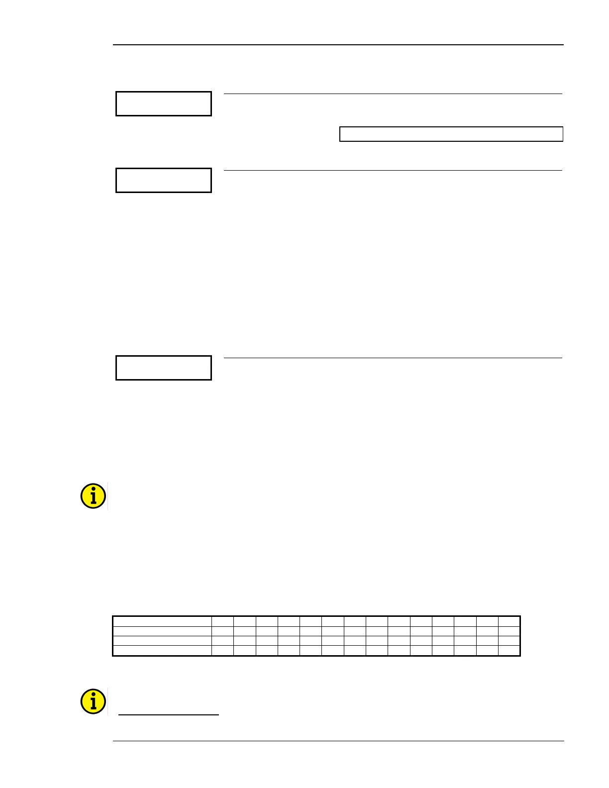
Discrete input 1 2 3 4 5 6 7 8 9 10 11 12 13 14
Name 1 2 3 4 5 6 7 8 9 A B C D E
Terminal 61 62 63 64 65 66 67 68 69 70 71 72 73 74
Function A A/C A/C A/C A A A/C A/C A A A A A A
A=Alarm input; A/C=Alarm or control input (dependent on the configuration)
NOTE
Operating current (NO): The relay is enabled (i.e. in the operating state) when current flows through the
coil. If a loss of the supply voltage occurs, a change of state will not occur in the relay and no trig-
gering of fault conditions occur. In this mode of operation the condition of the system should me

 Loading...


