Manual 37128A GCP-20 Series - Genset Control
Page 18/190 © Woodward
Chapter 5.
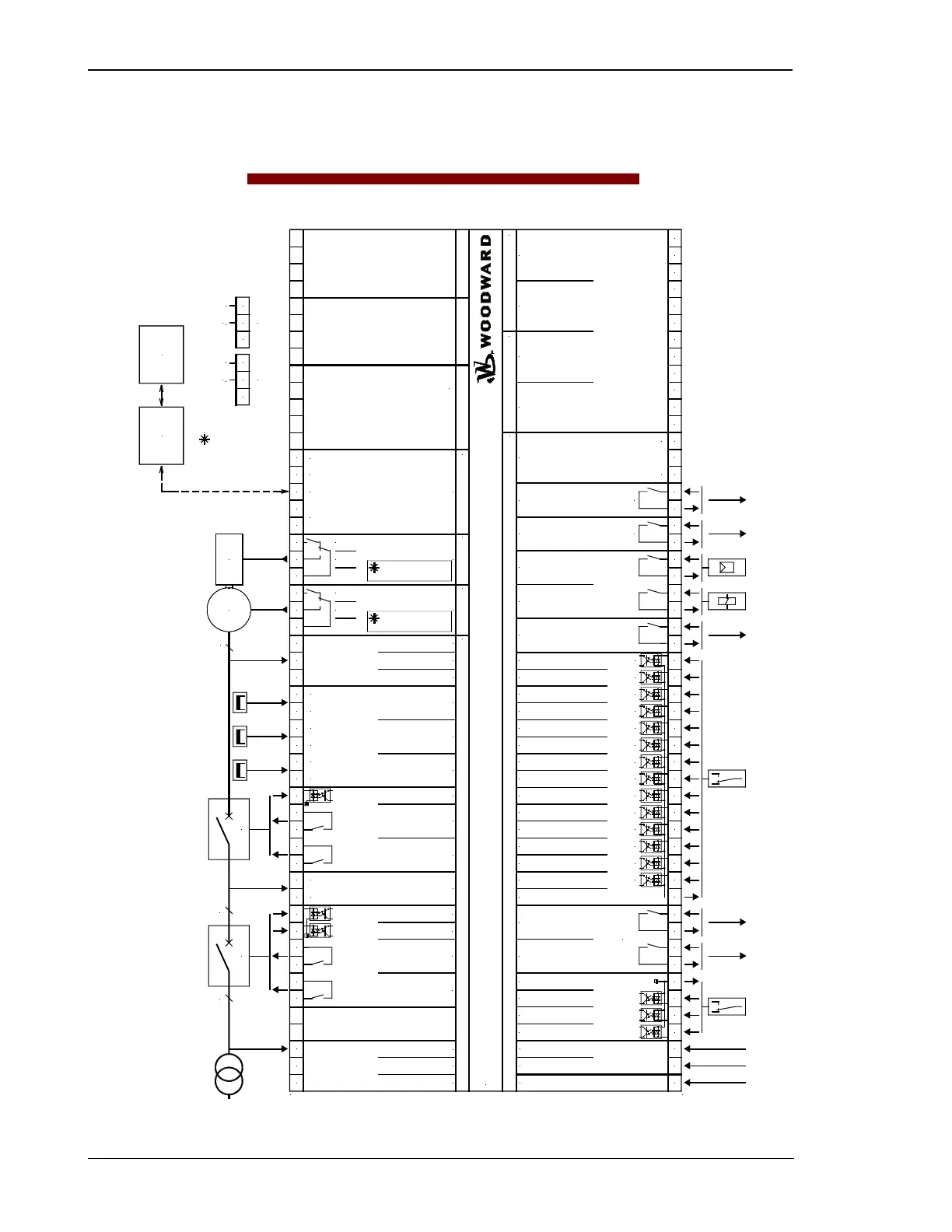
Wiring Diagrams
allall
A
U
GND
3
3
G
5
0 V DC
2005-07-21 / GCP-20 Anschlußplan Woodward gcp20ww-2905-ap.skf
1
9
6
7
8
A
B
C
D
E
50 51 52 53 54 23 24 41 14 15 4 25 2642 29 30 31 32 20 21 22 11 12 13 8 9 10 X1 X2 X3 X4 X5
0 1 2 3 5 6 7 33 34 35 36 60 61 62 63 64 65 66 67 68 69 70 71 18 19 43 44 45 46 90 91 92 93 94 95 96 97 98 99 100 101 102 103 104
L1
L2
s2 (l)
s1 (k)
s2 (l)
s1 (k)
s2 (l)
s1 (k)
12/24 V DC
N
131211
+/-5 V DC
A
U
GND
98
+/-3 V DC
10
higher
lower
Relay manager
(freely program-
mable relays)
Pickup
quasi-continuous controller with analog outputs
Drive
Printed 10/2001; subject to technical mocifications.
Mains voltage L1
Mains voltage L3
Mains voltage L2
Busbar voltage
GCB
Reply: GCB is open
higher
lower
Automatic 1
Ready for operation
Automatic 2
Multi-function terminal
Common (terminal 3/4/5/6/53/54)
Common
Input 1
(fault class 3: emergency STOP)
Input 5
Input 6
Input 7 or
Close GCB w/o engine monitoring
Input 8 or
Block emergency operation
Input 9
Input 10
Input 11
Input 12
Input 13
Input 14
Start relay / Gas valve
Starter
Relay 1
Relay 2
Command: open GCB
Generator current L1
Generator current L2
Generator current L3
Generator voltage L1
Generator voltage L2
Generator voltage L3
Command: close GCB
The PC configuration plug
is located on the side of the unit.
This is where the DPC cable
must be plugged in.
CAN bus interface
Guidance level
GND
switching/inductive
GND
CAN-H
CAN-L
Te r mi n a t i on
Relay 3
3837
Relay 4
484772 73 74
Input 4 or
Open transition
4
Input 3 or
Lock operation mode
3
Input 2 or
Crank terminate
2
3
40 16 1739
GCP-20 Genset Control Package
MCB
Release MCB
Command: open MCBCommand: open MCB
VOLTAGE
(three-position controller)
B/X alternative:
Analog controller output
SPEED
(three-position controller)
B/X/LSX alternative:
Analog controller output
Command: close MCB
Reply: MCB is open
Analog input 1 [T1]
VDO, 0 to 180 Ohm
(0 to 5/10 bar or 0 to 27/145 psi)
Analog input 2 [T2]
VDO, 0 to 380 Ohm (40 to 120 °C)
Analog input 3 [T3]
0/4 to 20 mA
Analog input 4 [T4]
0/4 to 20 mA
Control room
SPS
PC
GATEWAY
GW 4
Standard =
Centralized alarm
Standard =
Ignition / preglow
LS/X/LSX
all
all
X/LSXT2/X/LSX
Figure 5-1: Wiring diagram - GCP-20

 Loading...


