Manual 37128A GCP-20 Series - Genset Control
© Woodward Page 65/190
Operation of The Power Circuit Breakers
16
17
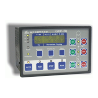
MCB ON / MCB OFF
only [GCP-20/22]
Color: green/red
Close MCB / open MCB (only available in [GCP-20/22])
Note: Only enabled if operating mode MANUAL or TEST has been se-
lected.
MCB ON..... Depending on which power circuit breaker logic has been set,
the MCB can be closed by pressing the "MCB ON" push-
button. This process can be aborted if the "MCB OFF" or
"GCB ON" push-button is actuated or the operating mode is
changed.
MCB OFF... By pressing the "MCB OFF" push-button, the mains power
circuit breaker can (depending on the power circuit breaker
logic) be opened, or synchronization of the MCB can be
aborted if started.
18
19
GCB ON / GCB OFF
Color: green/red
Close GCG / open GCB
Note: Only enabled if operating mode MANUAL or TEST has been se-
lected.
GCB ON...... Depending on which power circuit breaker logic has been set,
the GCB can be closed by pressing the "GCB ON" push-
button. This process can be aborted if the "GCB OFF" or
"MCB ON" push-button is actuated or the operating mode is
changed.
GCB OFF.... By pressing the "GCB OFF" push-button, the generator power
circuit breaker can (depending on the power circuit breaker
logic) be opened, or synchronization of the GCB can be
aborted if started.
Operating Mode Select Switch
20
21
START / STOP
Color: green/red
Engine start/stop
START........ Using this push-button the engine is started in MANUAL op-
erating mode. The starter and the fuel solenoid are activated
by pressing the push-button, whereby the starter is de-
activated after the firing speed has been reached, and the op-
erating magnet remains picked up. The push-button can now
be enabled.
STOP........... This push-button is used to stop the engine by de-activating
the fuel solenoid.
22 AUTO
Color: blue
Operating mode AUTOMATIC
The engine is automatically started and stopped, and the power circuit
breakers are automatically actuated. The two control inputs "Automatic 1"
and "Automatic 2" are used to specify various modes in "AUTOMATIC"
operating mode (also see description of control inputs). Emergency power
and sprinkler operation is carried out regardless of the status of the discrete
inputs "Automatic 1" and "Automatic 2".
• Discrete input "Automatic 1" set:
Active (real) power setpoint 1 is adjusted.
• Discrete input "Automatic 2" set:
Active (real) power setpoint 2 or an external setpoint (0/4 to 20 mA, 0 to
5/10 Vdc or interface) is adjusted (can be selected in configuration mode).
 Loading...
