Manual 37128A GCP-20 Series - Genset Control
Page 30/190 © Woodward
Interfaces (Options Su/Sb/Sf)
≡≡≡≡≡≡≡≡≡≡≡≡≡≡≡≡≡≡≡≡≡≡≡≡≡
Overview
Interface
RS485 interface
MOD bus RTU slave
GND
C
Interface
RS232 interface
GND
RTS
RxD
CTS
TxD
ACA B D E B
The transmitter drives the current.
Interface
TTY interface
RxD +
B (inverted)
A (non-inverted)
RxD -
NC
TxD +
TxD -
D E A CB D E
Interface
CAN bus
CAN-L
Termination
CAN-H
GND
CA B D E
Figure 6-19: Interfaces - overview
Terminal Description
Whether the terminals are designated X or Y depends on the configuration of the system. Please refer
to the wiring diagram (A = X/Y, B = X/Y, etc.)
A (X1/Y1) B (X2/Y2) C (X3/Y3) D (X4/Y4) E (X5/Y5)
RxD RTS GND CTS TxD RS-232
GND B A RS-485, MOD bus RTU slave
RxD- RxD+ NC TxD- TxD+ TTY (transm. drives the current)
GND CAN-H CAN-L CAN bus
Table 6-19: Interfaces - connection overview
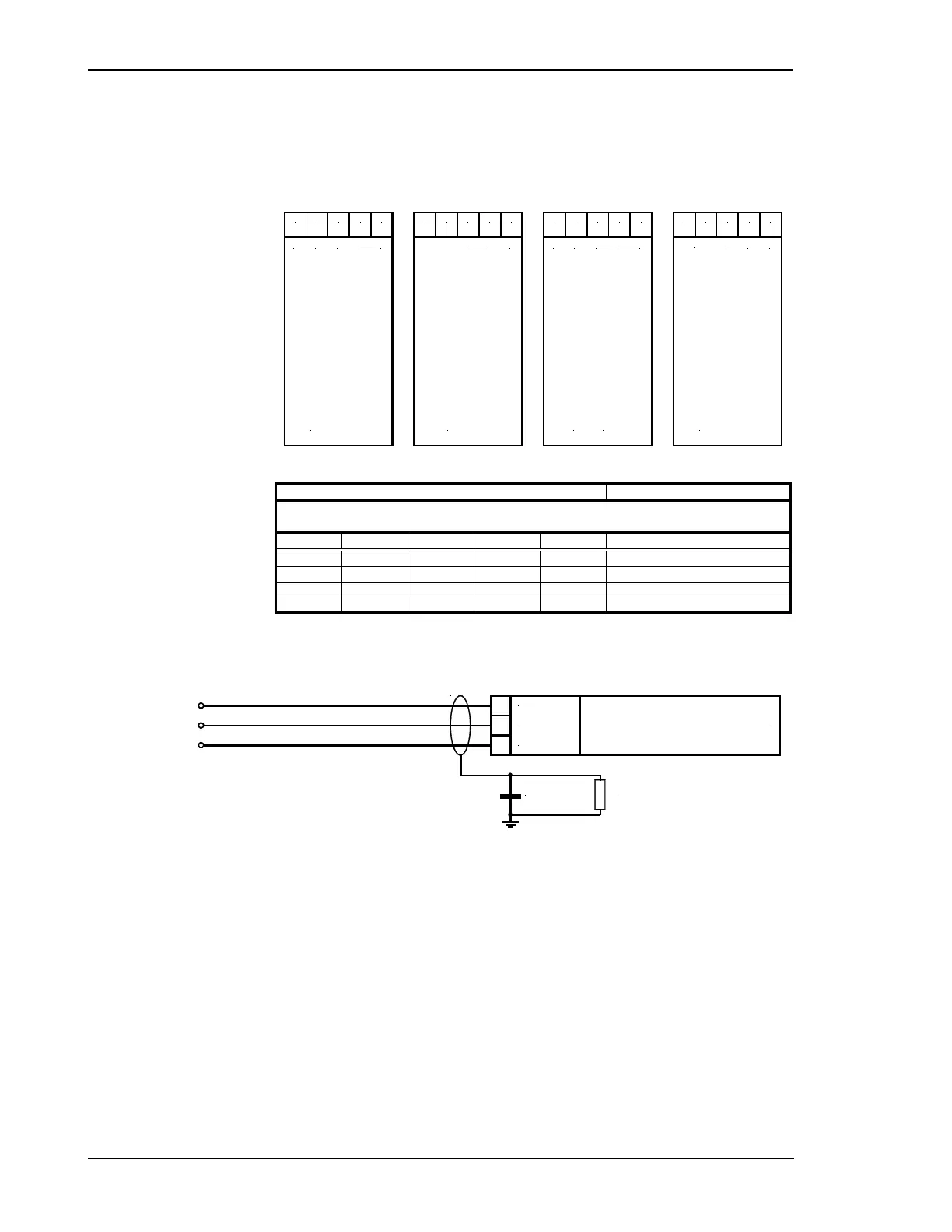
CAN Bus Shielding
Interface
CAN bus
CAN-H
CAN-L
GND
Shield
1 MOhm
0.01 uF
400 Vac
Figure 6-20: Interface - CAN bus shielding

 Loading...


